Prechamber Ignition System

a pre-chamber ignition and chamber technology, applied in combustion engines, ignition spark plugs, machines/engines, etc., can solve the problems of dead zones, flame kernel quenching, and insufficient fuel concentration in the pre-combustion chamber, and achieve the effect of increasing the ratio of fuel-oxidizer mixtur

Active Publication Date: 2014-04-17
PROMETHEUS APPLIED TECH
View PDF11 Cites 48 Cited by
  • Summary
  • Abstract
  • Description
  • Claims
  • Application Information

AI Technical Summary

Benefits of technology

[0010]Accordingly, a broad object of the invention can be to provide embodiments of the pre-combustion chamber of pre-combustion chamber units having configurations which generate flow fields and flow field forces inside the pre-combustion chamber which can achieve in comparison to conventional pre-chamber spark plugs one or more of: increased fuel-oxidizer mixture ratio in the electrode gap region, a flow field within the electrode gap which reduces flow of fuel-oxidizer mixtures toward flame quenching surfaces or creates a flow of fuel-oxidizer mixture directed or m...

Problems solved by technology

However, in general there remain a number of unresolved disadvantages with the use of conventional pre-chamber spark plugs in lean burn engines and specifically as described in U.S. Pat. No. 7,922,551, as follow.
A first substantial disadvantage with conventional pre-chamber spark plugs may be that the configuration of the pre-combustion chamber does not adequately concentrate fuel at the spark gap region of the spark plug.
One aspect of this disadvantage can be that the flow field forces within the spark gap region may be disorganized or even result in dead zones in which there is very little or no flow field.
This can result in flame kernel quenching as there are no flow field forces to move the flame kernel away from the quenching surfaces.
A second substantial disadvantage with conventional pre-chamber spark plugs may be that ...

Method used


Image

  • Prechamber Ignition System
  • Prechamber Ignition System
  • Prechamber Ignition System

Examples


example 1

Dual Bar-Dual Electrode Gap

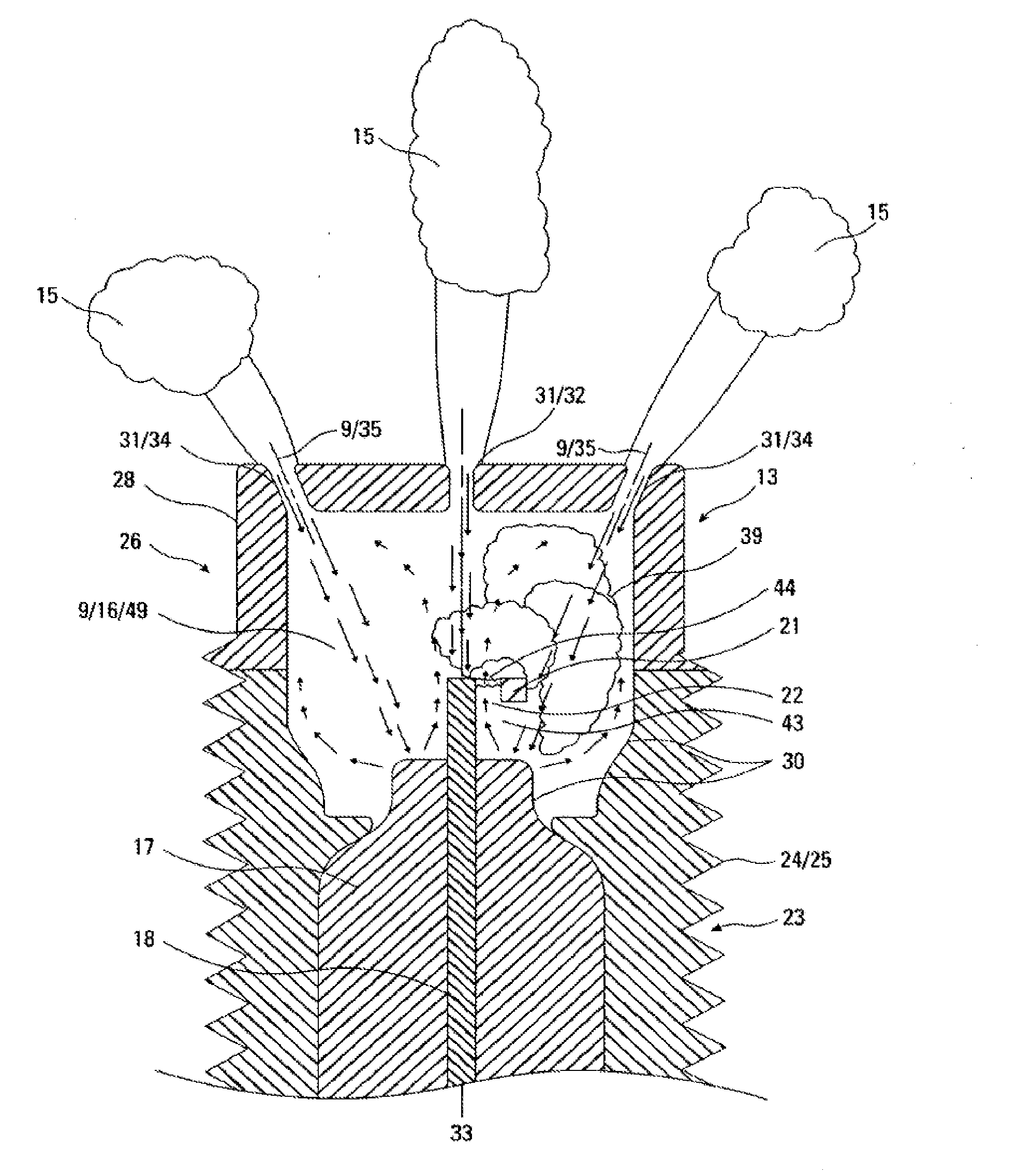
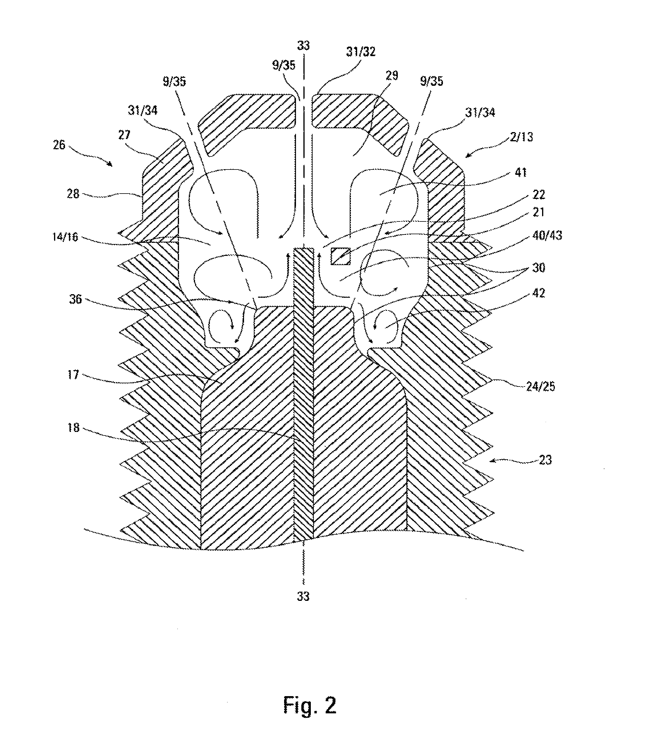
[0096]Now referring primarily to FIGS. 25 through 29, which provides a working example of a particular embodiment of the inventive pre-chamber unit (2) having a first electrode (18) in the form a central electrode (63) and a second electrode (21) in the form of a grounded dual bar electrode (54) (as shown in the example of FIG. 18) in the form of a first bar (61) and a second bar (62) disposed a distance apart with the first electrode (18) in the form of a central electrode (63) having a location between the first bar (61) and the second bar (62) to provide a dual electrode gap (as shown in the example of FIG. 18 and the examples of FIGS. 2 through 7). A central insulator (17) surrounds the central electrode (63). A metallic shell (23) encases the central electrode (63) and extends outwardly to provide a pre-combustion chamber (13) having a generally cylindrical shell external surface (24) and generally cylindrical shell pre-combustion chamber internal sur...

example 2

J-Gap Electrode

[0100]Now referring primarily to FIGS. 30 through 38, which provides a working example of particular embodiment of the inventive pre-chamber unit (2) having a first electrode (18) in the form a central electrode (63) and a second electrode (21) in the form of a grounded J-electrode (also shown in the example of FIGS. 19 and 10-11 and 15-17) disposed a distance axially above the central electrode (63) to provide an electrode gap (22) (as shown in the example of FIG. 30). A central insulator (17) surrounds the central electrode (63). A metallic shell (23) encases the central electrode (63) and extends outwardly to provide a pre-combustion chamber (13) having a generally cylindrical shell external surface (24) and generally cylindrical internal surface (30) surrounding the central insulator (17) and the first electrode (18) and the second electrode (21). The substantially closed end of the cylindrical pre-combustion chamber (13) having a flat pre-combustion chamber top (...


PUM


Abstract

Generally, embodiments of a pre-chamber unit having a pre-combustion chamber including one or more induction ports in a configuration which achieves flow fields and flow field forces inside the pre-combustion chamber which act to direct flame growth away quenching surface of the pre-combustion chamber.

Description

[0001]This application is the national stage for International Patent Cooperation Treaty Application PCT / US2011 / 002012, filed Dec. 30, 2011, entitled “Prechamber Ignition System,” which claims the benefit of U.S. Provisional Patent Application No. 61 / 460,337, filed Dec. 31, 2010, entitled “High efficiency ricochet effect passive chamber spark plug,” hereby incorporated by reference herein.I. TECHNICAL FIELD[0002]Generally, embodiments of a pre-chamber unit having a pre-combustion chamber including one or more induction ports in a configuration which achieves flow fields and flow field forces inside the pre-combustion chamber which direct flame growth away from quenching surfaces of the pre-combustion chamber.[0003]Specifically, embodiments of a pre-combustion chamber having an internal surface and one or more induction ports in a configuration which directs the fuel-oxidizer mixture of in-filling streams to ricochet from one or more locations on the internal surface of the pre-combu...

Claims


Application Information

Patent Timeline
IPC IPC(8): F02B19/08F02B19/12
CPCF02B19/12F02B19/08F02B19/1014F02B19/18F02P13/00Y02T10/12
Inventor SOTIROPOULOU, MARIA-EMMANUELLATOZZI, LUIGI P.
Owner PROMETHEUS APPLIED TECH
Why Eureka
Try Eureka