
Dialysis optimizing method

a dialysis and optimizing technology, applied in the field of dialysis optimizing method, can solve the problems of inability to accurately determine the dialysis dosage in real time, the method of saturating the dialysate with the blood side, and the complicated implementation of the dialysis machin

Inactive Publication Date: 2014-04-17
B BRAUN AVITUM
View PDF3 Cites 9 Cited by
  • Summary
  • Abstract
  • Description
  • Claims
  • Application Information

AI Technical Summary

Benefits of technology

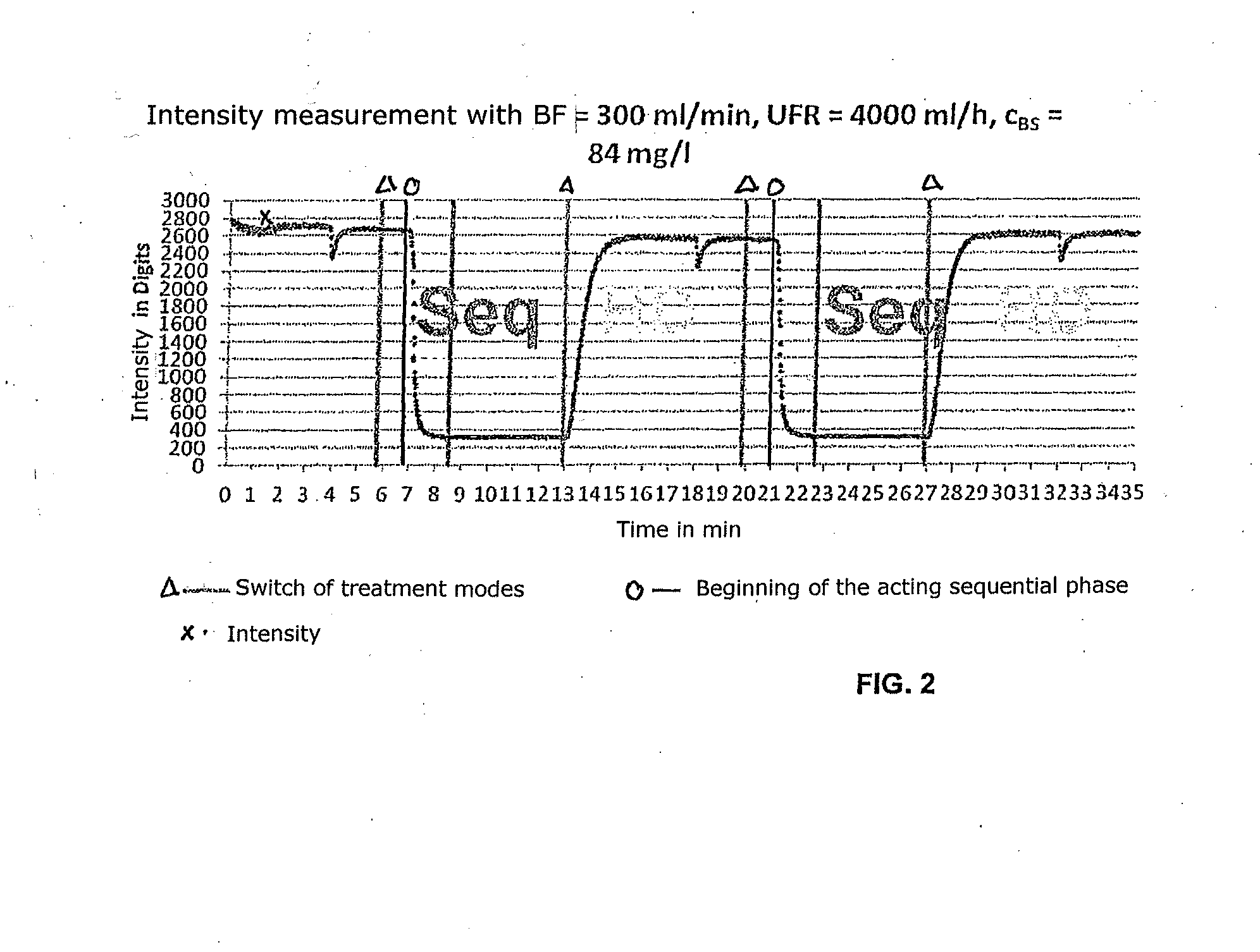
The present invention aims to develop a measuring method for uremic toxins in patients requiring dialysis. The method is designed to be non-invasive and to use existing methods on the dialysis side. The sensor for measuring concentration is less critical and can be positioned anywhere in the drain of the dialysate / ultra-filtrate. The method allows for faster determination of the concentration in the fluid in the dialysis fluid compartment of the dialyzer. By activating the sequential phase, the flow of dialysate via the dialyzer is stopped, and the concentration of uremic toxins can be measured through the ultra-filtrate. This avoids interruption in the dialysis therapy and allows for purifying the blood.

Problems solved by technology

As already described in the foregoing, methods determining the dialysis dosage in real time have weaknesses in the field of interpreting physiological changes in the patient and changes of the dialyser properties (purifying capacity) with respect to the calculation of the K*t / V value.
Another problem occurs in methods that establish the K*t / V value by taking blood samples on the basis of the urea concentration.
The drawback of the described method for saturating the dialysate with the blood-side concentration of uremic toxins is its complicated implementation in a dialysis machine.
In addition, the sensor by which the concentration is determined must be arranged at the corresponding circulating cycle which is complicated to realize on the machine side, because at the same time the volume of the circulating cycle has to be kept as small as possible.
It is an aim in this context that this measuring method can do without direct contact with the patient and thus cannot be considered to be interventional in this respect.

Method used


Image

  • Dialysis optimizing method
  • Dialysis optimizing method
  • Dialysis optimizing method

Examples


Embodiment Construction

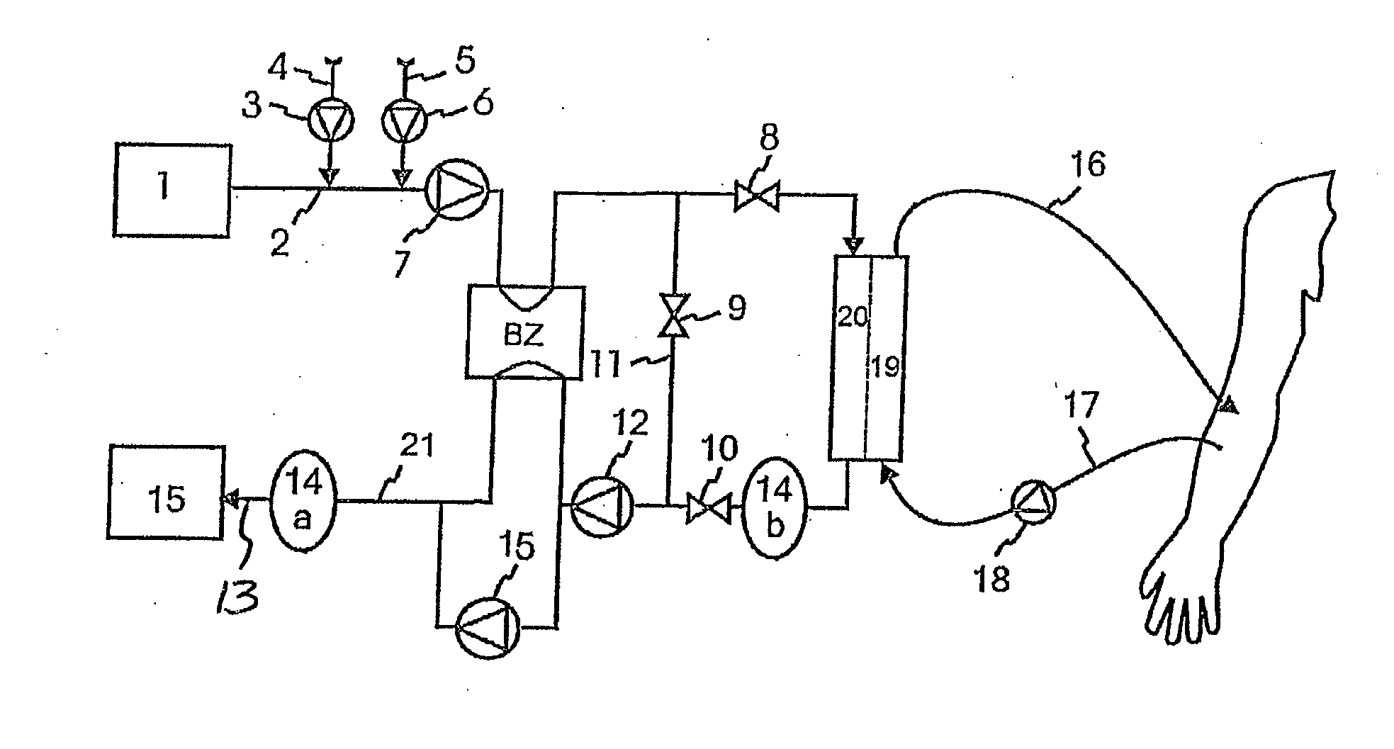
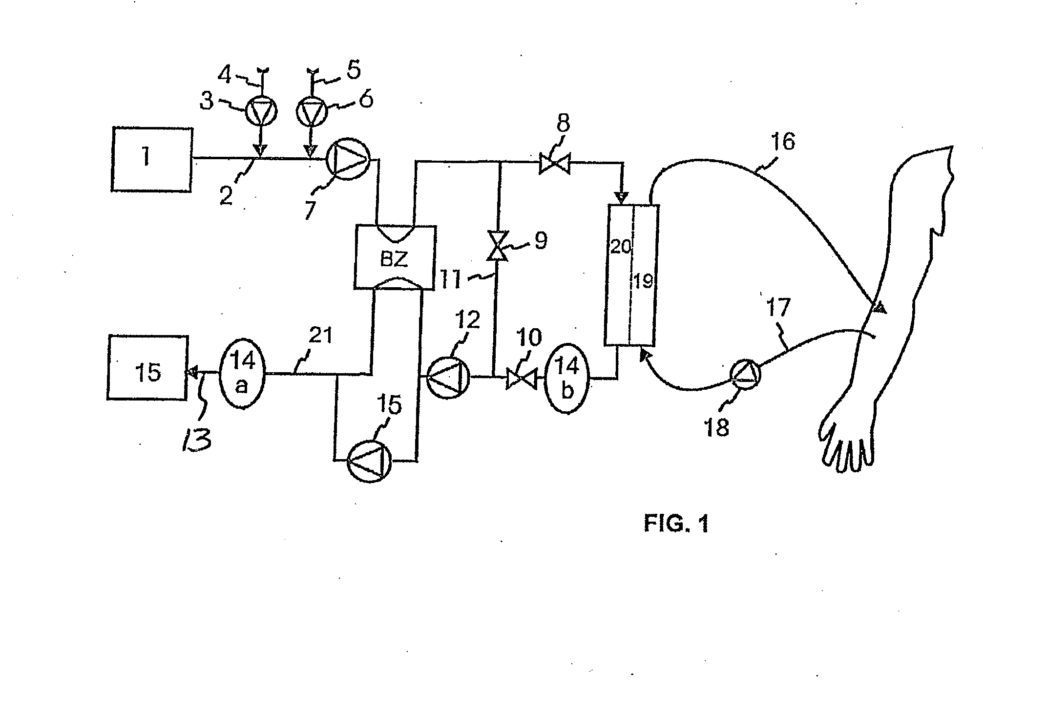
[0075]According to FIG. 1, the dialysis machine comprises at least one supply pump or flow pump dialyser input (FPE) 7 that supplies dialysis fluid via a supply line to a dialyser 19, at the input side thereof. The dialysis fluid is prepared in the present case by supplying water from a water treatment 1 via a water intake 2 of the supply pump 7, wherein a bicarbonate concentrate 4 is supplied by a bicarbonate pump 3 and an acid concentrate 5 is supplied by an acid pump 6 to the water. Moreover a balancing system BZ is interconnected in the supply line.

[0076]To an output side of the dialyser 19, 20 a drain line is connected leading to a first discharge pump or pump means at the dialyser output 12 which supplies used dialysis fluid (dialysate) to a collecting tank or dialysate drain 15 equally via the balancing system BZ. In parallel to the balancing system BZ a second booster pump 15 equally capable of conveying into the collecting tank / dialysate drain 15 is connected to the first d...


PUM


Abstract

A method as well as an apparatus is disclosed for determining the efficiency of a currently performed kidney replacement therapy on the dialysis side making use of a dialysis machine which in a first step is operated in a hemodialysis or hemodiafiltration process and in a second step is sequentially changed over to a hemofiltration process or is changed over to a sequential mode in which merely a flow from the blood compartment via the semipermeable membrane to the dialysis fluid compartment of the dialyser is generated in which, according to a third step, a sensor for determining or measuring the concentration at least of uremic toxins in the saturated dialysate or ultra-filtrate which is connected downstream of a dialyser on the dialysis side outputs corresponding measuring signals that are representative of the current concentration at least of uremic toxins in the blood to a calculation or determination unit.

Description

CROSS REFERENCE TO RELATED APPLICATIONS[0001]This application claims priority to German application DE 10 2012 109 858.1 filed Oct. 16, 2012, the contents of such application being incorporated by reference herein.FIELD OF THE INVENTION[0002]The present invention relates to a method as well as an apparatus for determining the efficiency of a currently carried out kidney replacement therapy and of the therapeutic apparatus.BACKGROUND OF THE INVENTION[0003]Patients suffering from renal insufficiency have to have uremic toxins accumulating in the patient's body over the time removed by means of an extracorporeal kidney replacement therapy, hereinafter referred to as dialysis treatment, if or as long as no kidney transplantation is envisaged. By such dialysis treatment blood is collected from the patient, is guided through an extracorporeal purifying device—the dialyser—and is subsequently returned into the patient's body. In the dialyser the blood to be purified then gets in contact wi...

Claims


Application Information

Patent Timeline
IPC IPC(8): A61M1/16
CPCA61M1/16A61M1/14A61M2202/0498A61M2205/3306A61M1/1609A61M1/1615A61M1/165A61M2205/3337A61M2230/65
Inventor MEIBAUM, JOERNSTROHHOEFER, CHRISTOF
Owner B BRAUN AVITUM
Learn More