Wire harness structure and electronic device control system

a wire harness and electronic device technology, applied in the direction of programme control, coupling device connection, instruments, etc., can solve the problems of increasing the cost of the wire harness, reducing the mounting capacity of the vehicle, and reducing the wiring property and weight. , to achieve the effect of improving design performance, reducing cost, and improving productivity

Active Publication Date: 2014-04-17
YAZAKI CORP
View PDF2 Cites 26 Cited by
  • Summary
  • Abstract
  • Description
  • Claims
  • Application Information

AI Technical Summary

Benefits of technology

[0017]As described above, according to the invention described in the first aspect and the sixth aspect, the plurality of power supply units which supply power to the respective electronic devices in accordance with the control signal from the electronic control unit is connected to the power wire and the ground wire drawn out from the relay connector, the power wire and the ground wire each including one wire. That is, the power supply unit is provided at outside of the relay connector. Thus, the relay connector does not increase in size even if the number of electronic devices controlled by the electronic control unit is increased, and also, it eliminates the need for preparing the relay connector for each of combinations of the plurality of electronic devices to be mounted to the vehicle, thereby achieving the standardization of the relay connector. Consequently, there is provided the wire harness structure having improved design performance and improved productivity and which can reduce the cost, and there is also provided the electronic device control system having such wire harness structure.
[0018]As described above, according to the invention described in the second aspect, the power supply unit is embedded in the connector connecting the electronic device to the power wire, the ground wire and the signal wires. Thus, the electronic device and the connector can be electrically-connected to each other by connector coupling the electronic device with the connector in which the power supply unit is embedded, thereby improving the assembling workability. In addition, the connector in which the power supply unit is embedded can be commonly-used for the plurality of electronic devices, thus the connector can be standardized, thereby improving design performance and productivity and thus reducing the cost.
[0019]As described above, according to the invention described in the third aspect, the power wire can be electrically-connected to the signal wires transmitting the control signal corresponding to one electronic device of the plurality of electronic devices, simply by press-fitting the power wire, the ground wire and the signal wires transmitting the control signal corresponding to one electronic device of the plurality of electronic devices to the plurality of solderless terminals, respectively. Thus, the assembling workability is improved even more.
[0020]As described above, according to the invention described in the fourth aspect, the connector includes the base plate portion having one surface arranged to be mount with the plurality of solderless terminals, and the other surface of the base plate portion is provided with the groove portion formed concave with respect to the other surface, the groove portion being arranged to house the signal wires transmitting the control signal corresponding to the electronic device other than said one electronic device. Thus, the signal wires transmitting the control signal corresponding to the electronic device other than said one electronic device can be wired in a non-voluminous and organized fashion, thereby downsizing the wire harness structure.
[0021]As described above, according to the invention described in the fifth aspect, the first cover portion covering the plurality of solderless terminals mounted on the one surface of the base plate portion and the second cover portion covering an opening of the groove portion are provided. Thus, the power wire, the signal wires transmitting control signal corresponding to one electronic device of the plurality of electronic device and the signal wires transmitting control signal corresponding to the electronic device other than said one electronic device, which are press-fitted to the plurality of solderless terminals, can be protected and fixed between the first cover portion and the second cover portion.
[0022]As described above, according to the invention described in the seventh aspect, the relay connector includes the integrated control unit arranged to control such that the supply quantity of power to the plurality of electronic devices does not exceed a predetermined constant value. Thus, the supply quantity of power to the plurality of electronic devices can be equalized. Consequently, the signal wire drawn out from the relay connector can have a small diameter and can be downsized.

Problems solved by technology

As a result, there are problems of an increase in the cost of the wire harness, a decrease in wiring property and an increase in weight, to name a few.
Thus, there is a problem that the size of the relay connector 106 itself is increased, causing a decrease in mountability to the vehicle.
Thus, it is difficult to standardize the relay connector 106, and thus the kind of the relay connector 106 is increased, thereby increasing the cost.

Method used


Image

  • Wire harness structure and electronic device control system
  • Wire harness structure and electronic device control system
  • Wire harness structure and electronic device control system

Examples


Embodiment Construction

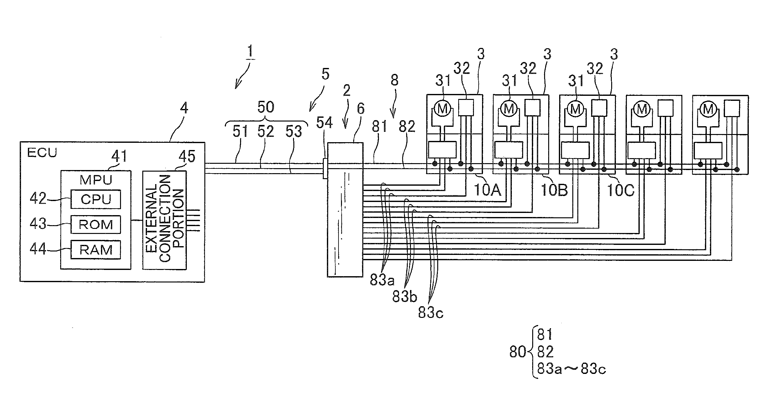
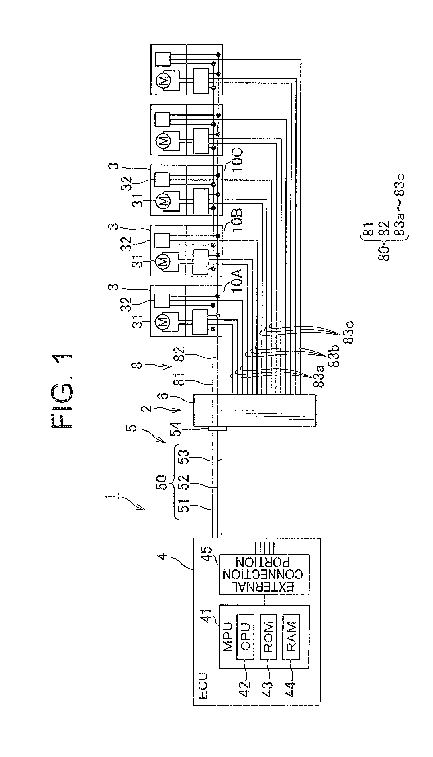
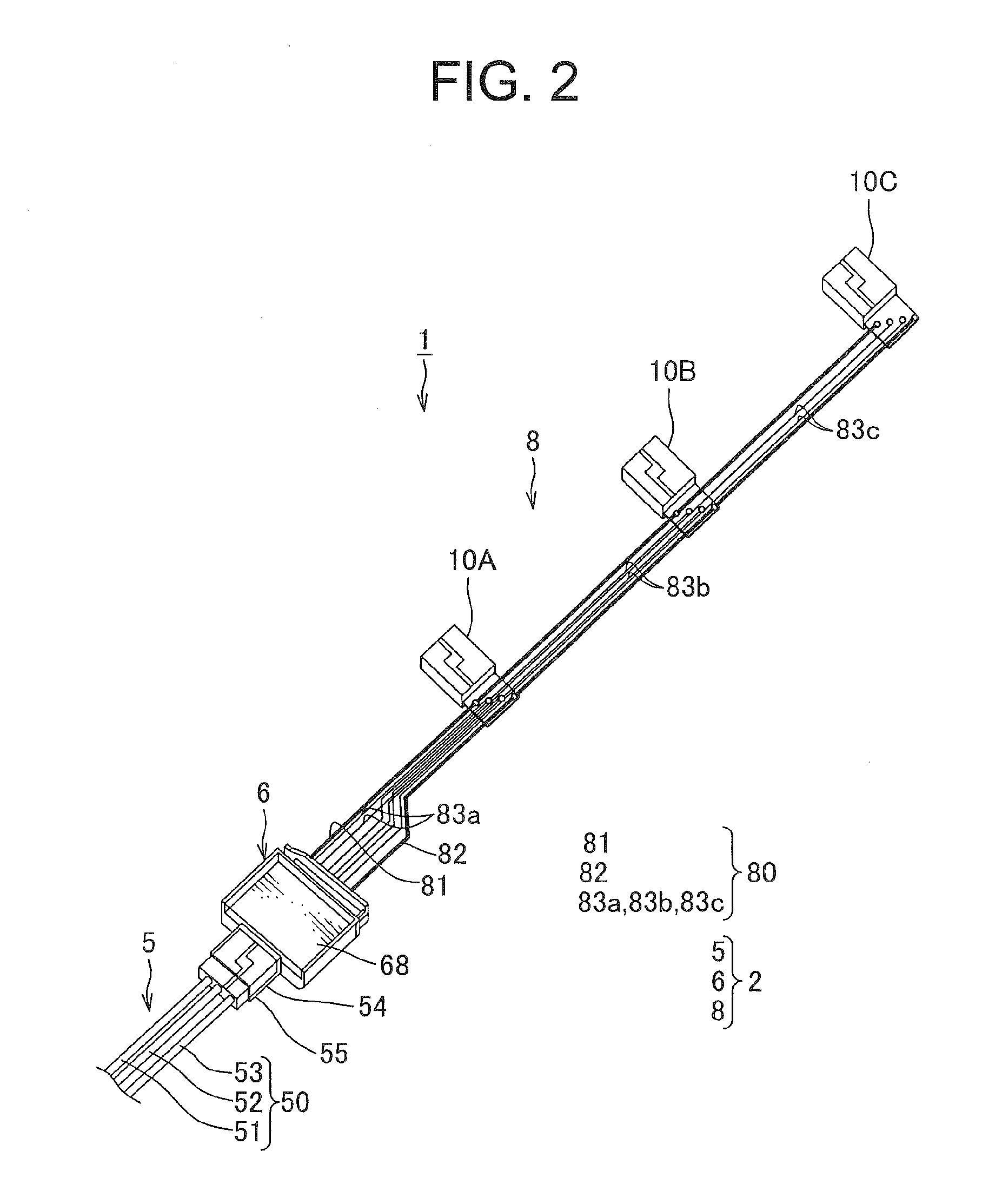
[0035]In the following, one embodiment of an electronic device control system and a wire harness structure constituting the electronic device control system according to the present invention are explained in reference to FIGS. 1 through 7.

[0036]An electronic device control system shown in FIG. 1 is mounted to a vehicle not shown. As shown in FIG. 1, this electronic device control system 1 includes a plurality of loads 3 as electronic devices, an electronic control unit (ECU) 4 and a wire harness structure 2. This electronic device control system 1 is a system arranged to communicatably-connect the plurality of loads 3 with the ECU 4 using the wire harness structure 2 to control the plurality of loads 3 by the ECU 4.

[0037]The plurality of loads 3 is a device of various kinds to be controlled by the ECU 4. In one example, in case of being mounted to a vehicle, the plurality of loads 3 includes: a motor body 31 such as a slide motor, a front up motor, a seat lift motor, a reclining mo...


PUM


Abstract

Provide is a wire harness which does not increase in size with increase in number of electronic devices controlled by an electronic control unit and can standardize a relay connector, and an electronic device control system including such wire harness. A wire harness structure (2) communicatably-connects electronic devices (3) mounted on a vehicle to an electronic control unit (4) controlling the electronic devices, and includes a relay connector (6, 6A, 6B) relaying a control signal from the electronic control unit to the electronic devices, a power wire (81) and a ground wire (82) drawn out from the relay connector, power supply units connected to the power wire and the ground wire, and sets of signal wires (83a, 83b, 83c) transmitting the control signal to each power supply unit arranged to supply power to the electronic device and drive the electronic device according to the control signal from the signal wire.

Description

TECHNICAL FIELD[0001]The present invention relates to a wire harness structure arranged to communicatably-connect a plurality of electronic devices to be mounted on a vehicle to an electronic control unit controlling these electronic devices, and relates to an electronic device control system having said wire harness structure.BACKGROUND ART[0002]Vehicles such as a passenger vehicle and a freight vehicle are mounted with various electronic devices constituting an air conditioner, a wiper, a power window and such. These electronic devices are electrically-connected to an electronic control unit (ECU) including a computer and such by a wire harness. Electric power and a control signal and such are transmitted between these electronic devices and the ECU via the wire harness. Such wire harness includes a plurality of electric wires and a connector for receiving a terminal fitting connected to an end of the electric wire.[0003]Conventionally, the ECU includes an input-output portion per...

Claims


Application Information

Patent Timeline
Patent Type & Authority Applications(United States)
IPC IPC(8): B60R16/02
CPCB60R16/0207B60R16/0315G05B2219/21076G05B2219/2637H01R4/2433H01R13/665H04L12/40013H04L12/40045H04L12/6418H04L2012/40273
Inventor ITO, KENAOKI, YOSHIHITOSATAKE, SHUJI
Owner YAZAKI CORP
Why Eureka
Try Eureka