Printing machine and method for adjusting a web tension

Active Publication Date: 2014-04-17
KOENIG & BAUER AG
View PDF6 Cites 38 Cited by
  • Summary
  • Abstract
  • Description
  • Claims
  • Application Information

AI Technical Summary

Benefits of technology

[0014]The advantages to be achieved by the invention consist particularly in enabling a highly effective adjustment of a web tension of the printing material web. This is accomplished, for example, by means of a preferred multiplicity of driven rotating bodies and/or corresponding impression rollers which are in contact with said bodies and/or preferably a series of measuring devices embodied as measuring rollers. In addition to avoiding web breaks and/or sagging, this preferable adjustment of web tension serves to improve color registration and/or register, since stretching of the printing material web is directly dependent on forces acting on the printing material web. A further advantage is that usable printed products can be produced from the start of a printing operation, because the at least one print head preferably ejects printing ink at all transport speeds of the printing material web 02, and preferably ejects it at all accelerations of the transport speed of the printing material web 02, particularly negative and/or positive accelerations. This is enabled particularly by the precise adjustment of web tension. A savings of time and material is thereby realized, since less paper spoilage and/or less unprinted printing material 02 is produced.
[0015]A further advantage results from the preferred arrangement of at least two web edge aligners, which enable an especially precise conveyance of a printing material web, resulting in a particularly high quality printed product.
[0016]A further adva

Problems solved by technology

In contrast to printing materials such as paper or metal, t

Method used


Image

  • Printing machine and method for adjusting a web tension
  • Printing machine and method for adjusting a web tension
  • Printing machine and method for adjusting a web tension

Examples


Example

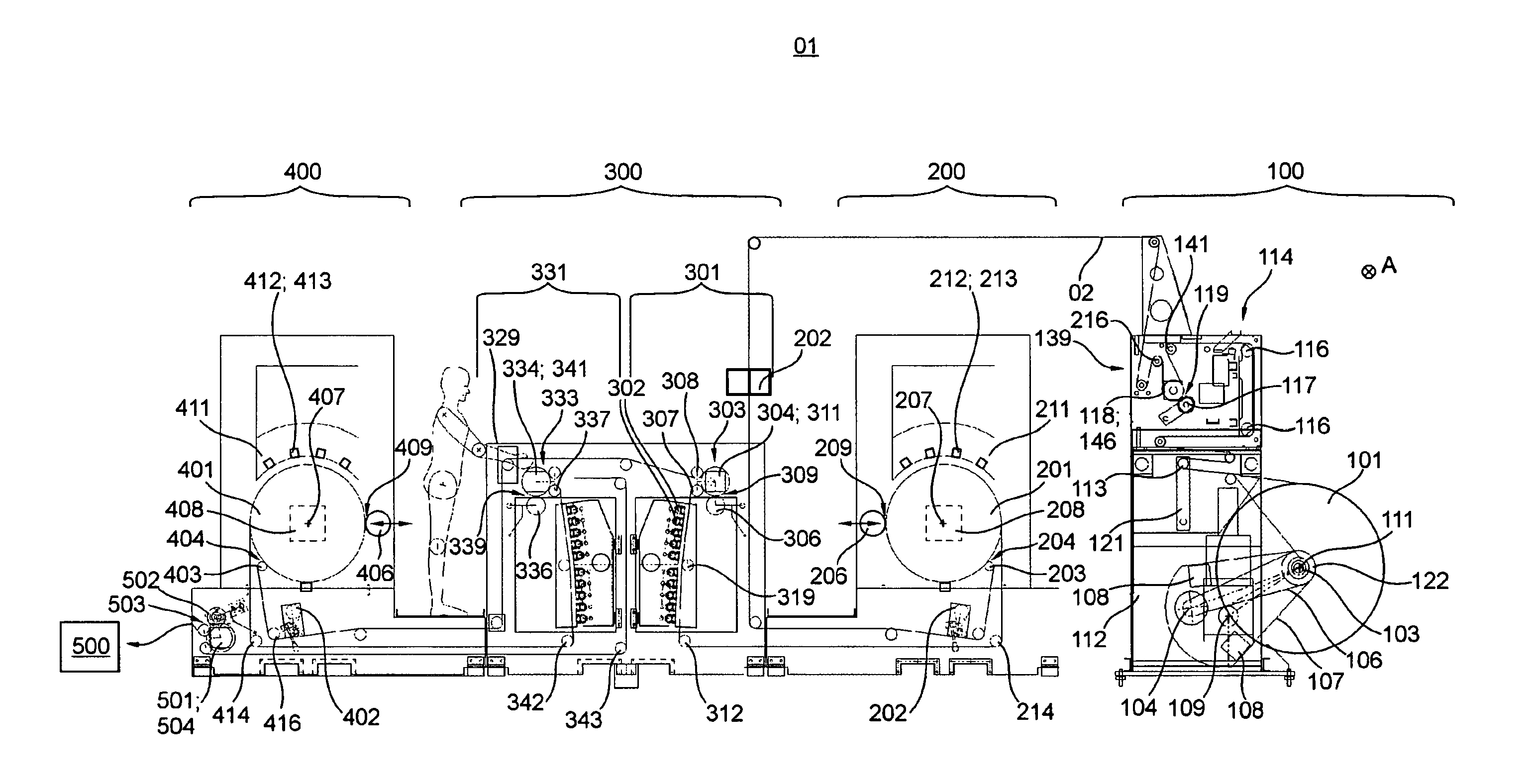
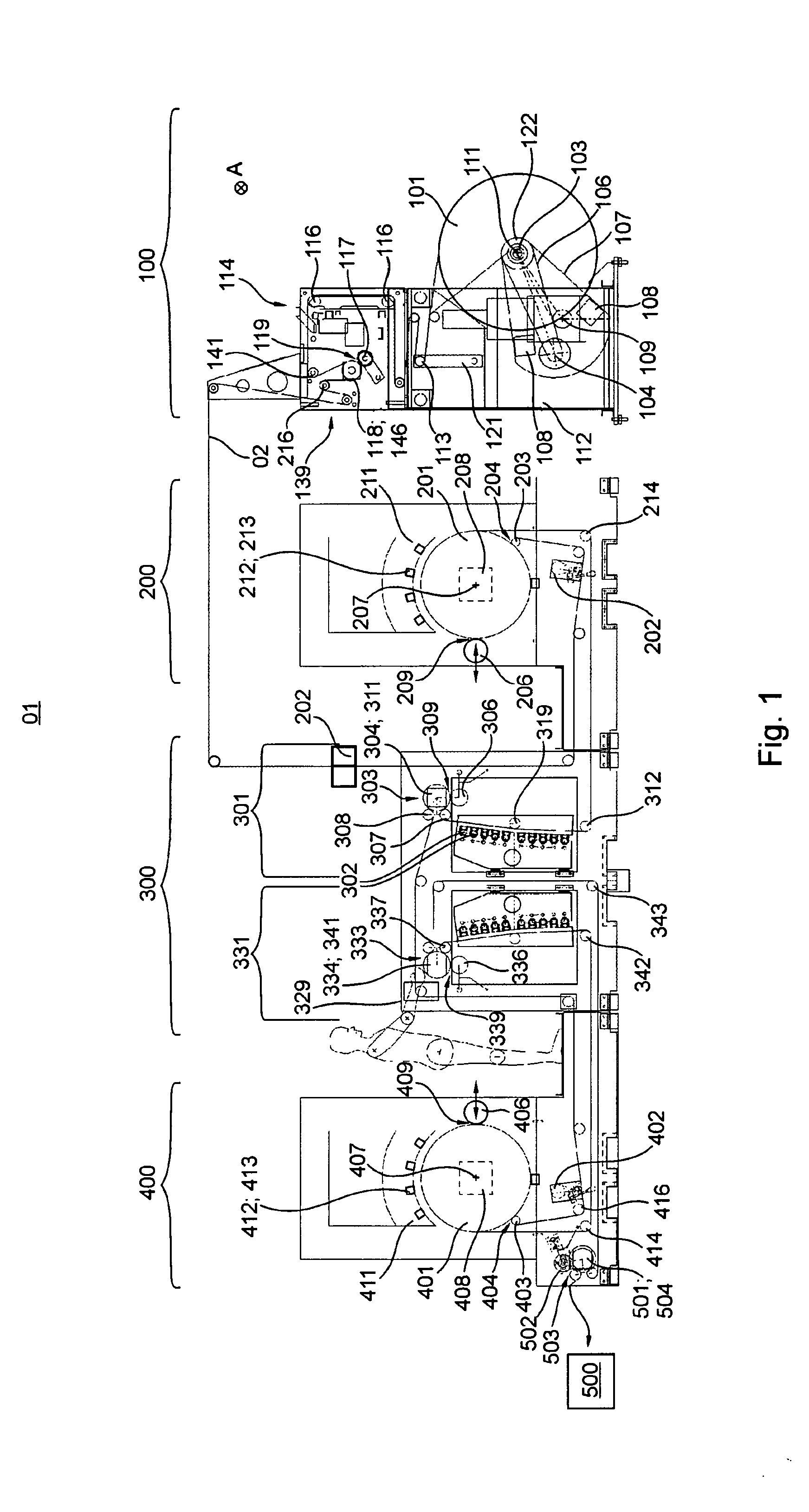
[0029]A printing machine 01 has at least one printing material source 100, at least one first printing unit 200, preferably at least one first dryer 301, preferably at least one second printing unit 400 and preferably at least one second dryer 331 and at least one post-processing apparatus 500. The printing machine 01 is preferably embodied as an inkjet printing machine 01. The printing machine 01 is preferably embodied as a web-fed printing machine 01, and more preferably as a web-fed inkjet printing machine 01. The printing machine 01 is embodied, for example, as a rotary printing machine 01, for example, as a web-fed rotary printing machine 01, particularly as a web-fed rotary inkjet printing machine 01. In the case of a web-fed printing machine 01, the printing material source 100 is embodied as a roll unwinding device 100. In the case of a sheet-fed rotary printing machine, the printing material source 100 is embodied as a sheet feeder. In the printing material source 100, prin...


PUM


Abstract

The invention relates to a printing machine having at least one printer unit comprising at least one inkjet printhead, a central printing cylinder, and a drive motor of its own dedicated to the central printing cylinder. A conveying path of a printing material web through the printing machine has at least one first section and one second section, each defined by contact points of the printing material, which have motor-powered rotation bodies. At least the first section has a dedicated first measuring device for measuring a web tension of the printing material web in the first section. At least the second section has a dedicated second measuring device for measuring the web tension of the printing material web in the second section. A machine controller is arranged, by means of which the web tension in at least the first section and/or in the second section of the conveying path of the printing material web can be adjusted and/or is adjusted, taking into consideration at least both a measuring result from the first measuring device and a measuring result from the second measuring device. The invention further relates to a method for adjusting a web tension of a printing material web.

Description

CROSS REFERENCE TO RELATED APPLICATIONS[0001]This application is the U.S. national phase, under 35 USC 371, of PCT / EP2012 / 057979, filed May 2, 2012, published as WO2012 / 163614 A1 on Dec. 6, 2012, and claiming priority to DE 10 2011 076 899.8, filed Jun. 1, 2011 and to DE 10 2011 088 776.8, filed Dec. 16, 2011, the disclosures of which are expressly incorporated herein by reference.FIELD OF THE INVENTION[0002]The invention relates to a printing machine and to a method for adjusting a web tension.BACKGROUND OF THE INVENTION[0003]Various printing methods that can be used in rotary printing machines are known. One such printing method is inkjet printing. In this method, individual droplets of printing ink are ejected from nozzles in print heads and transferred to a printing material so as to produce a printed image on the printing material. By controlling a plurality of nozzles individually, different printed images can be produced. No set printing forme is used, thus each individual pr...

Claims


Application Information

Patent Timeline
IPC IPC(8): B41J15/16
CPCB41J15/16B41J3/60B41J11/002B41J15/165B41J11/00214B41J11/00216B41J11/0022B41J11/0015
Inventor HACKER, CHRISTOPH ALBANHUPPMANN, FRANK EBERHARDWANDER, STEFAN
Owner KOENIG & BAUER AG
Why Eureka
Try Eureka