High-Output LED Light Fixture

a led light fixture and high-output technology, applied in the field of street and roadway light fixtures, can solve the problems of heat dissipation particularly challenging problems of high-luminance led light fixtures using led modules as light sources, etc., to facilitate heat conduction, facilitate heat conduction, and facilitate heat conduction

Active Publication Date: 2014-04-17
IDEAL IND LIGHTING LLC
View PDF2 Cites 26 Cited by
  • Summary
  • Abstract
  • Description
  • Claims
  • Application Information

AI Technical Summary

Benefits of technology

[0016]The edge-adjacent fins extending from each one of the beyond-module portions of the heat-sink base may be a single edge-adjacent fin, such two edge-adjacent fins forming the opposite lateral sides of the heat sink, which may be an extrusion. In some of such embodiments, the heat-sink base has a thickness at positions adjacent to the edge-adjacent fins that is greater than the thickness of the base at positions adjacent to some of the middle fins, thereby to facilitate conduction of heat laterally away from the module.
[0017]In certain embodiments, each of the edge-adjacent fins has a base-adjacent proximal portion integrally joined to the heat-sink base and a distal edge remote therefrom, the proximal portions of the edge-adjacent fins being thicker than the proximal portions of at least some of the middle fins, thereby to facilitate conduction of heat away from the module. The heat-sink base may have a thickness at positions adjacent to the edge-adjacent fins that is greater than the thickness of the base at positions adjacent to some of the middle fins, thereby to facilitate conduction of heat laterally away from the module.
[0019]In certain embodiments, the plurality of heat sinks are beside one another in positions such that the beyond-module portion of each of the heat sinks is adjacent to but spaced from the beyond-module portion of another of the heat sinks. Such arrangement further facilitates flow of cool air to the heat-dissipating surfaces of the heat sinks and thermal isolation of the heat sinks from one another.
[0026]In some embodiments, the inventive mounting assembly facilitates adjustment of the light fixture to a selected one plurality of possible orientations during installation. In some of such embodiments, the gripper grips the gripping region such that the light fixture is held in a selected one of the plurality of possible orientations.

Problems solved by technology

High-luminance light fixtures using LED modules as light source present particularly challenging problems.
One particularly challenging problem for high-luminance LED light fixtures relates to heat dissipation.

Method used


Image

  • High-Output LED Light Fixture
  • High-Output LED Light Fixture
  • High-Output LED Light Fixture

Examples


Embodiment Construction

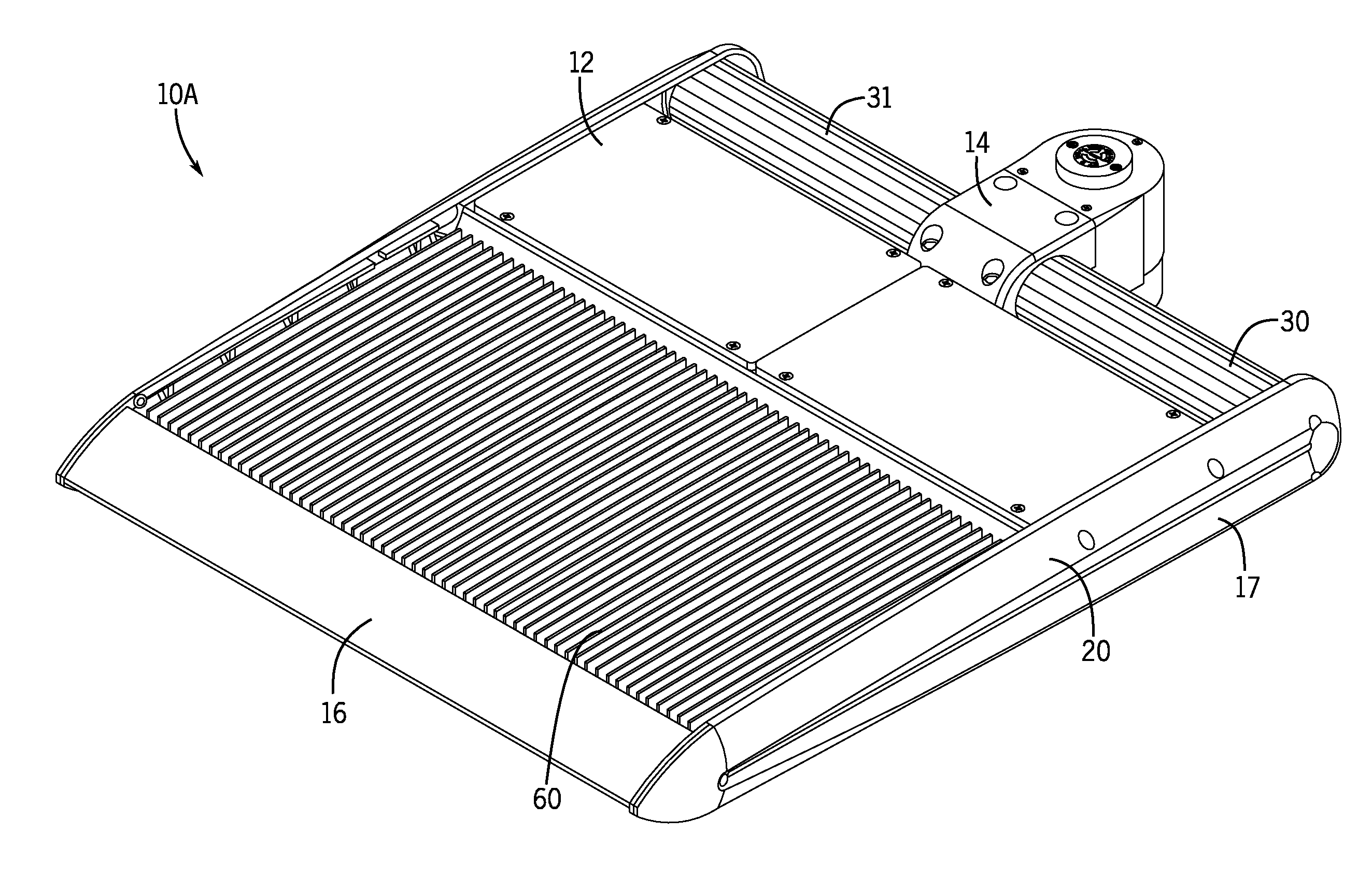
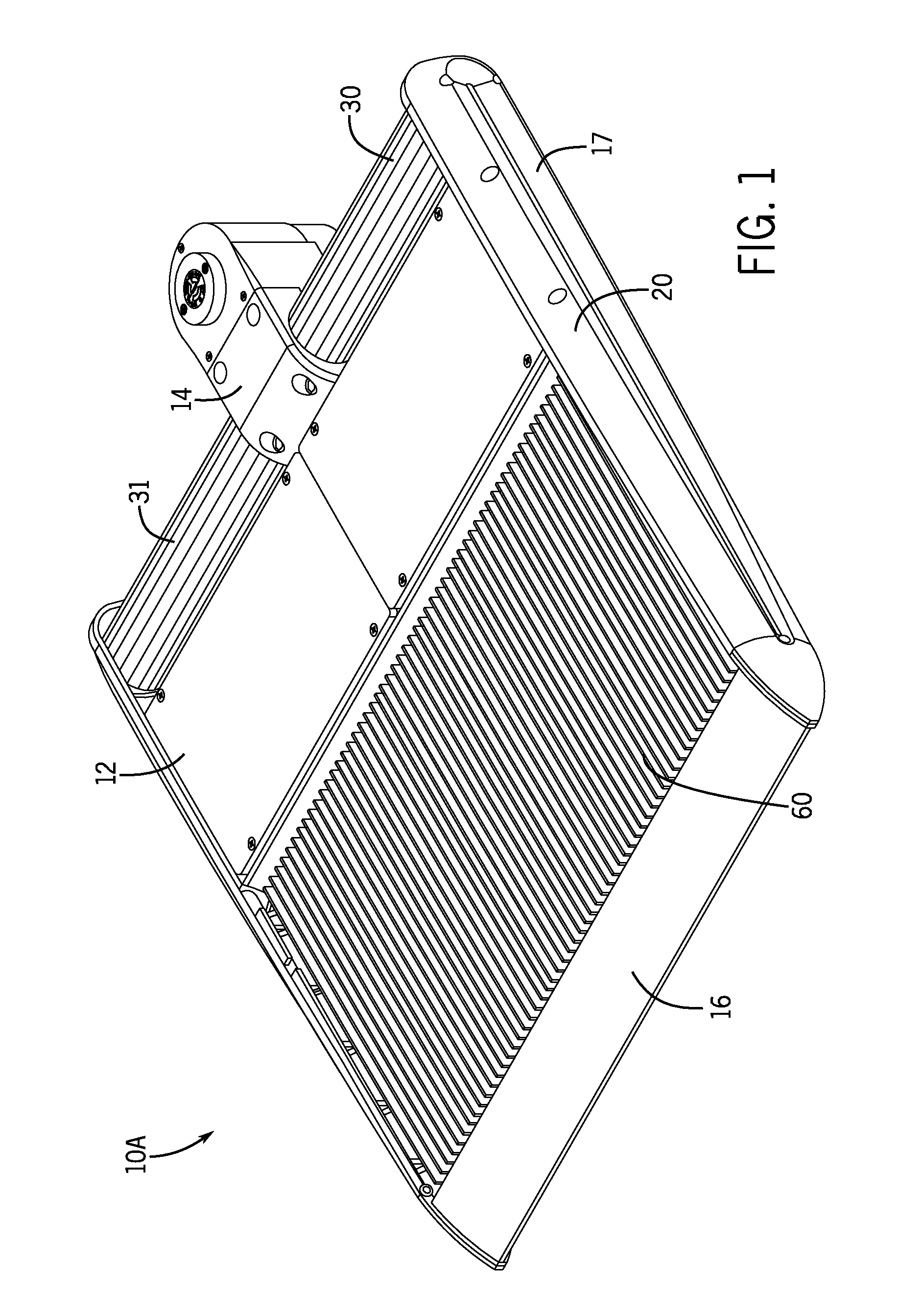
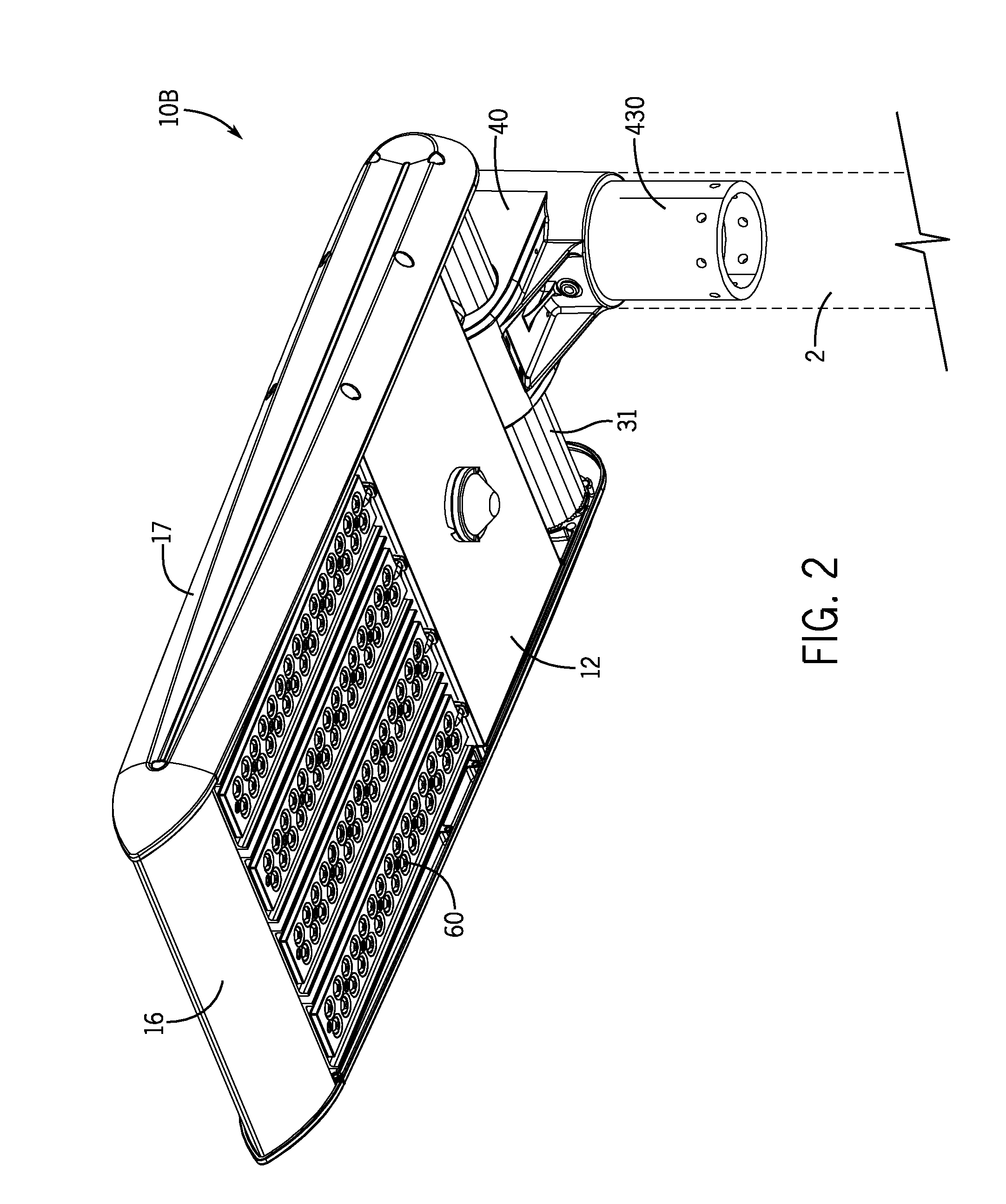
[0066]FIGS. 1-11 illustrate an LED light fixtures 10A and 10B (the latter in FIG. 2 only) in accordance with this invention. Common or similar parts are given the same numbers in the drawings of both embodiments, and the light fixtures are often referred to by the numeral 10, without the A or B lettering used in the drawings, and in the singular for convenience.

[0067]FIGS. 1-4 show that light fixture 10 including an LED assembly 60 which is open to air / water flow thereover. As seen in FIGS. 2 and 4, LED assembly 60 has a plurality of LED-array modules 61 each secured to an individual LED heat sink 62 (best seen in FIG. 3) which has first and second heat-sink ends 63 and 64 best seen in FIG. 5.

[0068]It is seen in FIGS. 2 and 4 that LED light fixture 10 includes a plurality of heat-sink-mounted LED-array modules 61. Each module 61 engages an LED-adjacent surface 680 of heat-sink base 68 for transfer of heat from module 61. Heat-sink heat-dissipating surfaces include fins 620 which ext...


PUM


Abstract

An LED floodlight fixture LED light fixture including a plurality of heat-sink-mounted LED-array modules, each module engaging an LED-adjacent surface of a heat-sink base for transfer of heat from the module, and at least one venting aperture through the heat-sink base to provide air ingress to the heat-dissipating surfaces adjacent to the aperture. The LED light fixture may include a plurality of heat sinks, each heat sink with its own heat-dissipating surfaces and heat-sink base which has one of the LED-array modules engaged thereon. The heat-sink base is wider than the module thereon such that the heat-sink base includes a beyond-module portion. The venting aperture(s) is / are through the beyond-module portion of the heat-sink base. The inventive light fixture may include a housing and an LED assembly which includes the heat-sink-mounted LED-array modules. The LED assembly and the housing form a venting gap therebetween to provide air ingress along the heat-sink base to the heat-dissipating surfaces.

Description

RELATED APPLICATION[0001]This application is based in part on U.S. Provisional Application Ser. No. 61 / 624,211, filed Apr. 13, 2012. This application is also a continuation-in-part of patent application Ser. No. 13 / 333,198, filed Dec. 21, 2011, now U.S. Pat. No. 8,313,222, issued Nov. 20, 2012, which in turn is a continuation of patent application Ser. No. 12 / 418,364, filed Apr. 3, 2009, now U.S. Pat. No. 8,092,049, issued Jan. 10, 2012, which in turn is based in part on U.S. Provisional Application Ser. No. 61 / 042,690, filed Apr. 4, 2008. The entirety of the contents of all such applications are incorporated herein by reference.FIELD OF THE INVENTION[0002]This invention relates to light fixtures and, more particularly, to street and roadway light fixtures and the like, including light fixtures for illumination of large areas. More particularly, this invention relates to such light fixtures which utilize LEDs as light source.BACKGROUND OF THE INVENTION[0003]Light fixtures such as fl...

Claims


Application Information

Patent Timeline
Patent Type & Authority Applications(United States)
IPC IPC(8): F21V29/00F21V15/01
CPCF21V29/2293F21V15/011F21V29/2206F21V31/03F21K9/00F21S2/005F21S8/086F21V15/013F21V15/015F21V17/107F21V19/0055F21V23/002F21W2131/103F21V29/74F21V29/75F21V29/763F21Y2105/10F21Y2115/10F21Y2113/00F21V19/04F21V29/83F21V29/56
Inventor KINNUNE, BRIANRUUD, ALAN J.WILCOX, KURTGOELZ, DAVID P.
Owner IDEAL IND LIGHTING LLC
Why Eureka
Try Eureka