

Ultraviolet treatment device
a treatment device and ultraviolet technology, applied in the field of ultraviolet treatment devices, can solve the problems of limited performance of devices designed for applications such as sterilization of bacteria, viruses, spores or other pathogens, and it is not practical to fabricate treatment systems using such conventional methods, so as to improve the effectiveness of sterilization of bacteria, viruses, spores and other pathogens, and facilitate the heating time. , the effect of effective sterilization
- Summary
- Abstract
- Description
- Claims
- Application Information
AI Technical Summary
Benefits of technology
Problems solved by technology
Method used
Image

Examples
example 1
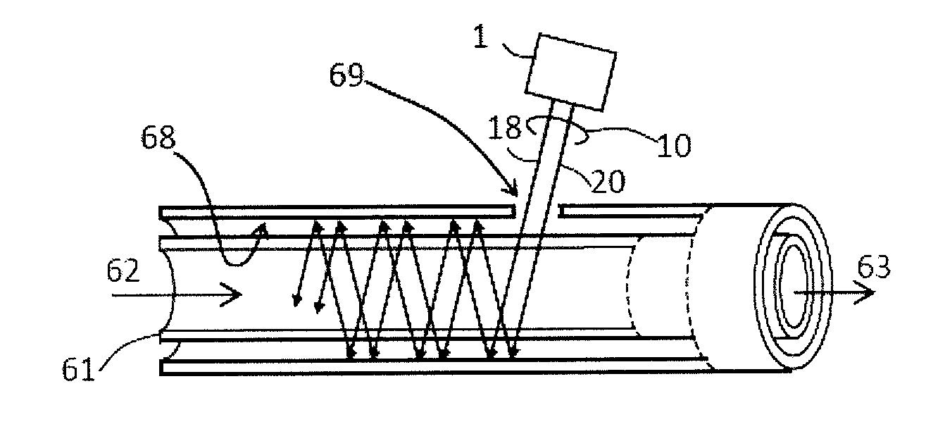
[0122]Another exemplary embodiment of an ultraviolet light source 1 for treatment of a fluid, solid or surface is depicted in the schematic diagram of FIG. 6. The light source includes one or more LEDs 17 emitting UV light 18 with a peak wavelength approximately greater than or equal to 250 nm and less than or equal to 400 nm. For example, the device contains a plurality of LEDs 17 emitting UV light 18 with a peak wavelength of approximately 265 nm. The LEDs 17 may include AlyInxGa1-x-yN semiconductor materials (019 emitting UV light 20. The laser light sources 19 include a laser diode 21 emitting light 22 with a peak wavelength approximately greater than or equal to 360 nm and less than 500 nm. The laser diode may include AlyInxGa1-x-yN semiconductor materials (022 has a peak wavelength of approximately 442 nm. The light 22 passes through a frequency-doubling component 23. As the light 22 passes through the frequency-doubling component 23, some or all of the light 22 is converted i...
example 2
[0128]Another exemplary embodiment of an ultraviolet light source 1 for treatment of a fluid, solid or surface is depicted in the schematic diagram of FIG. 10. This embodiment is similar to the previous embodiment and the similar features will not be repeated in the description. The distribution of wavelengths of the combined light 10 are different in this embodiment of Example 2. The UV light source 1 includes one or more LEDs 17 emitting UV light 18 with a peak wavelength approximately greater than or equal to 250 nm and less than or equal to 400 nm. In this exemplary embodiment, the light source 1 contains a plurality of LEDs 17 emitting UV light 18 with a peak wavelength of approximately 260 nm. The device further includes a plurality of two or more laser light sources: at least one of a first UV laser light source 19 and at least one of a second UV laser light source 31. The first UV laser light source 19 includes a laser first diode 21 emitting light 22, and a first frequency-...
example 3
[0133]Another exemplary embodiment of an ultraviolet light source 1 for treatment of a fluid, solid or surface is depicted in the schematic diagram of FIG. 14. The embodiment of Example 3 is similar to the previous embodiments and the similar features will not be repeated in the description. The distribution of wavelengths of the combined light 10 is different in the embodiment of Example 3. The UV light source 1 contains a set of a plurality, and at least two or more, LEDs: at least one of a first type of LED 17 and at least one of a second type of LED 44. The first type of LED 17 emits a first portion of the first component of UV light 18. The second type of LED 44 emits a second portion of the first component of UV light 45. The peak wavelength of the first portion of the first component of UV light 18 and the second portion of the first component of UV light 45 are different and are each approximately greater than or equal to 250 nm and less than or equal to 400 nm. In this exam...
PUM
 Abstract
Description
Claims
Application Information