Oil mist separator

Active Publication Date: 2014-04-24
TOYOTA BOSHOKU KK
View PDF4 Cites 17 Cited by
  • Summary
  • Abstract
  • Description
  • Claims
  • Application Information

AI Technical Summary

Benefits of technology

The present patent relates to an oil mist separator for a vehicle. The oil mist separator includes a separator body with a bottom wall and side walls, a gas introduction part, a gas discharge part, a separation unit, and dams. The dams are formed along the gas flow path to block the separated oil from flowing to the downstream side and prevent the oil from being brought to the downstream side by the flow of the blow-by gas. The dams also prevent the flow of the blow-by gas near the bottom wall of the separator body, ensuring that the separated oil does not flow out of the gas discharge part. The oil mist separator can effectively store separated oil in an oil storage part, preventing it from flowing out of the gas discharge part. This results in a more efficient oil separation process and prevents the oily material from causing damage or malfunction in the vehicle's system.

Problems solved by technology

However, the blow-by gas contains an oil component for lubricating the internal combustion engine in mist form, and when the blow-by gas containing the oil component is burnt, disadvantageously, the amount of lubricating oil decreases, and white smoke occurs due to combustion of the oil component.

Method used


Image

  • Oil mist separator
  • Oil mist separator
  • Oil mist separator

Examples


embodiments

[0041]Embodiments of the present invention will be specifically described below with reference to figures. In this embodiment, an oil mist separator mounted in a vehicle internal combustion engine is exemplified.

(1) Configuration of the Oil Mist Separator

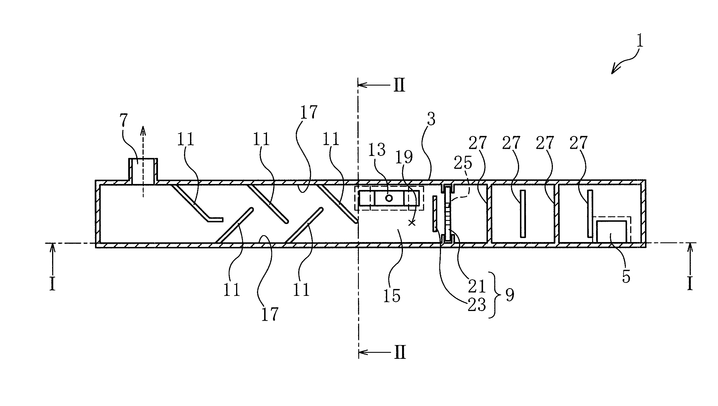
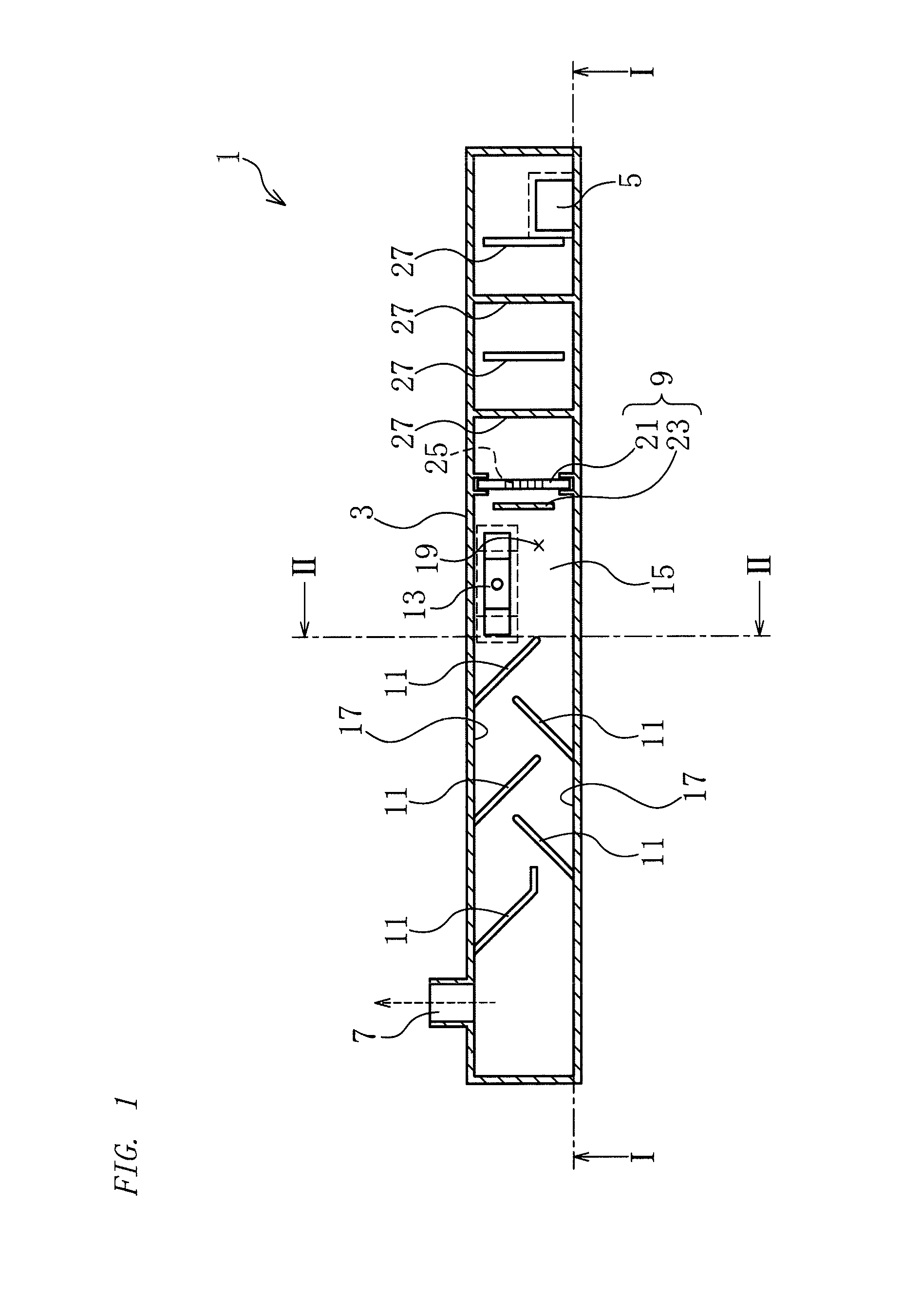
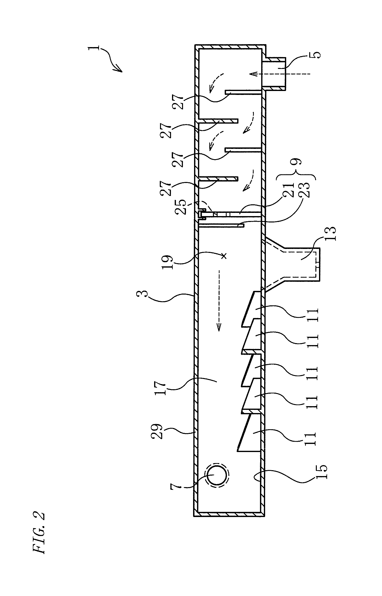
[0042]An oil mist separator 1 in accordance with this embodiment is an oil mist separator for separating mist oil contained in blow-by gas from an internal combustion engine. As shown in FIGS. 1 to 3, the oil mist separator 1 includes a separator body 3, a gas introduction part 5, a gas discharge part 7, a separation unit 9, dams 11, and an oil discharge part 13.

[0043]The separator body 3 is substantially shaped like a square tube including a bottom wall 15 and a pair of side walls 17 erected from sides of the bottom wall 15. A space inside the separator body 3 acts as a gas flow path 19 through which the blow-by gas flows. The gas introduction part 5 is provided on the bottom wall 15 at one end of the separator body 3. The gas intr...


PUM


Abstract

An oil mist separator includes: a separator body having a gas flow path; a gas introduction part introducing the blow-by gas into the separator body; a gas discharge part discharging the blow-by gas from the separator body; a separation unit separating oil from the blow-by gas; dams provided on the bottom wall of the separator body downstream of the separation unit in the gas flow path and configured to block the oil separated from flowing to the downstream side; and an oil discharge part provided upstream of the dams in the gas flow path and configured to discharge the oil separated from the separator body, wherein the dams are formed along the gas flow path so as to alternately extend from the pair of side walls, and the dams extend such that tip ends of the dams are located beyond a center of the gas flow path.

Description

TECHNICAL FIELD[0001]The present invention relates to an oil mist separator. In particular, the present invention relates to an oil mist separator capable of suppressing separated oil from moving along a bottom surface toward a gas outlet.BACKGROUND ART[0002]A PCV (positive crankcase ventilation) system by which blow-by gas leaking from a combustion chamber of an internal combustion engine into a crankcase through a gap between a piston and a cylinder is introduced into an induction system has been conventionally known. The PCV system sends the blow-by gas as incomplete combustion gas into the combustion chamber again, thereby preventing emission of fuel components and carbon monoxide in the blow-by gas into air.[0003]However, the blow-by gas contains an oil component for lubricating the internal combustion engine in mist form, and when the blow-by gas containing the oil component is burnt, disadvantageously, the amount of lubricating oil decreases, and white smoke occurs due to com...

Claims


Application Information

Patent Timeline
IPC IPC(8): B01D45/08
CPCB01D45/08F01M13/04F01M2013/0433F01M2013/0461F01M2013/0488B01D46/0089
Inventor HORIUCHI, YOJI
Owner TOYOTA BOSHOKU KK
Why Eureka
Try Eureka