Method For Identifying A Fault In An Electrical Machine

Active Publication Date: 2014-04-24
ABB (SCHWEIZ) AG
View PDF3 Cites 28 Cited by
  • Summary
  • Abstract
  • Description
  • Claims
  • Application Information

AI Technical Summary

Benefits of technology

[0020]According to a second aspect of the invention, there is provided a monitoring system for identifying a fault in an electrical machine having a rotor and a stator. The monitoring system comprises a first sensor arranged to measure vibration in a first radial direction of the stator, and a second sensor arranged to measure vibration in a second radial direction of the stator. A processor receives measurement signals from the first sensor and the second sensor. The processor comprises a first algorithm for detecting from the measurement signals a first vibration frequency and a mode shape of the vibration at the first vibration frequency. The processor further comprises a second algorithm for identifying a fault condition of the electrical machine from the combination of the first vibration frequency and the mode shape. With a monitoring s

Problems solved by technology

For example, with the measurement setup disclosed in D1, FIG. 15 it is not eve

Method used


Image

  • Method For Identifying A Fault In An Electrical Machine
  • Method For Identifying A Fault In An Electrical Machine
  • Method For Identifying A Fault In An Electrical Machine

Examples


Embodiment Construction

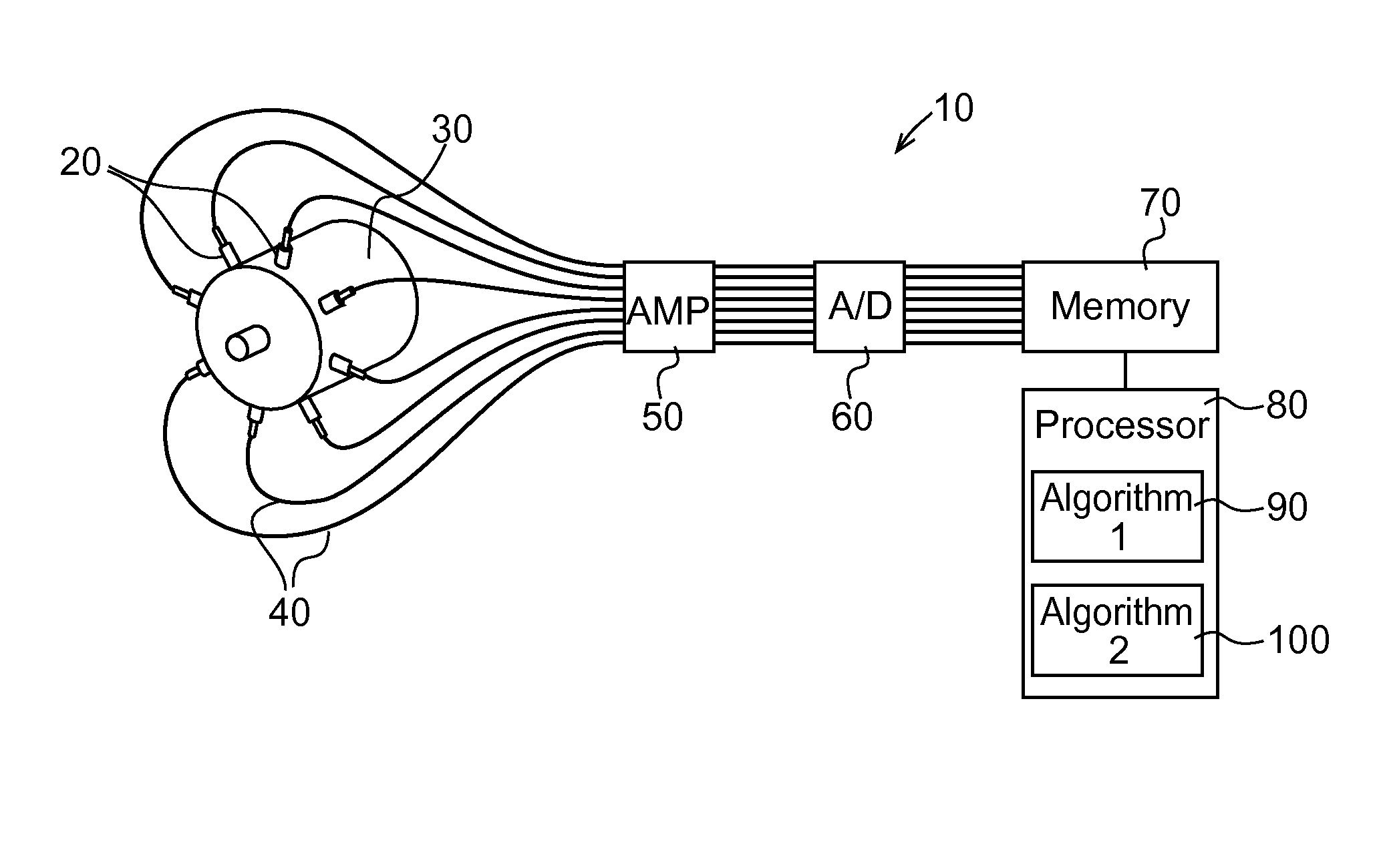
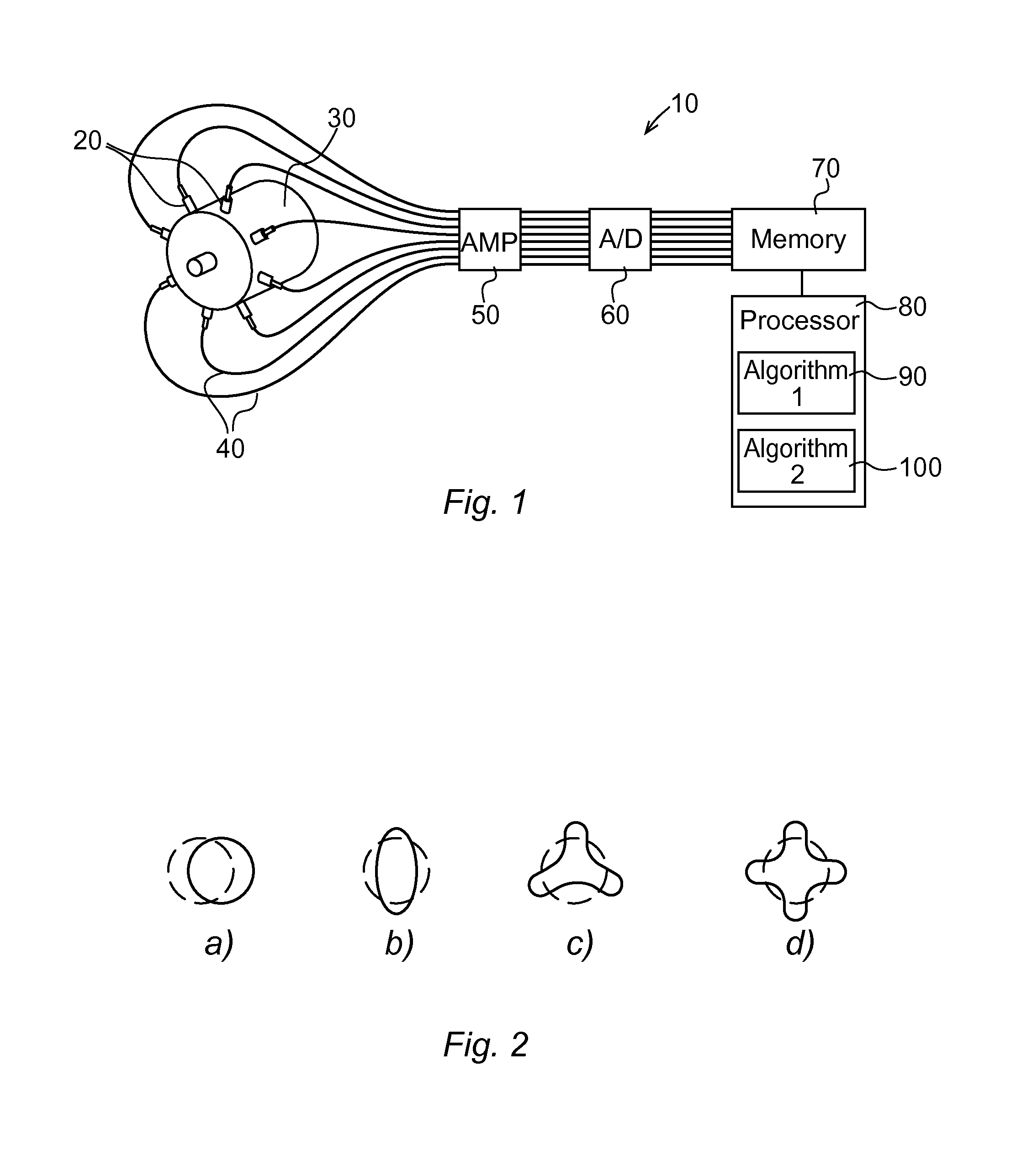
[0028]Referring to FIG. 1, a measurement installation 10 for measuring vibrations in an electrical machine is shown. There are eight accelerometers 20 evenly distributed about the circumference of a stator 30. A great number of accelerometers 20 enables the detection of high number modes, so the more accelerometers 20 the better fault identification ability the measurement installation 10 has. However, since we are mainly interested in low number modes (from 1 to 4), eight accelerometers 20 or even less should be enough. The accelerometers 20 are connected by measurement cables 40 to an amplifier 50, and further to an A / D converter 60. The accelerometers 20 give the vibration information in time space i.e. the acceleration as a function of time. In addition, angular position of each accelerometer 20 is known. The measurement results are finally stored in digital form in a computer memory 70 for further processing.

[0029]A processor 80 receives and processes the measurement results fr...


PUM


Abstract

For identifying a fault in an electrical machine vibration is measured in a plurality of radial directions of the stator. On the basis of the vibration measurements a vibration frequency and a mode shape of the vibration at this frequency is determined. Characteristics of the vibration in terms of both the vibration frequency and the mode shape are used to identify a fault condition of the electrical machine.

Description

FIELD OF THE INVENTION[0001]The present invention relates to a method and a system for identifying a fault in an electrical machine.BACKGROUND OF THE INVENTION[0002]Like any technical device, electrical machines may suffer from different kind of faults, either of mechanical or electrical character. Since electrical machines have a moving element in form of a rotor, many of the most common fault conditions cause vibrations to the machine. It is known that different fault conditions cause different kind of vibrations. In turn, it follows that by knowing what kind of vibration a certain fault condition causes, it is possible to detect the fault by monitoring the vibration characteristics of the machine.[0003]Vibration monitoring has been conventionally used to detect mechanical faults in electrical machines. This monitoring method has been successful e.g. in detecting bearing defects. However, one has not been able to detect electrical faults in a satisfactory way by means of vibration...

Claims


Application Information

Patent Timeline
IPC IPC(8): G01H17/00
CPCG01H17/00G01H1/003G01H1/006
Inventor RODRIGUEZ, PEDRO
Owner ABB (SCHWEIZ) AG
Why Eureka
Try Eureka