Air seed meter housing with seed path relief

a technology of air seed meter and path relief, which is applied in the field of mechanical devices, can solve the problems of duplicate dispense, failure to dispense at all, and inability to draw seeds, so as to reduce the likelihood of a seed cell being skipped, reduce the likelihood of a seed cell being drawn, and increase the accuracy of planting seeds

Active Publication Date: 2014-04-24
KINZE MFG INC
View PDF1 Cites 6 Cited by
  • Summary
  • Abstract
  • Description
  • Claims
  • Application Information

AI Technical Summary

Benefits of technology

[0012]It is therefore a primary object, feature, and / or advantage of the present invention to improve on or overcome the deficiencies in the art.
[0013]It is another object, feature, and / or advantage of the present invention to reduce the likelihood that a seed drawn onto or against a seed cell can be knocked free of the seed cell as it passes by the adjacent housing wall.
[0014]It is yet another object, feature, and / or advantage of the present invention to reduce the likelihood that a seed cell is skipped, missed or otherwise left vacant.
[0015]It is still another object, feature, and / or advantage of the present invention to increase the accuracy of planting seed.
[0016]It is a further object, feature, and / or advantage of the present invention to provide an offset portion of the seed meter housing to reduce the likelihood of the outer wall knocking the seed from a seed cell.
[0017]It is still a further object, feature, and / or advantage of the present invention to provide a relief member positioned at an offset portion of the seed meter housing outer wall to increase the suction at the seed cell at the offset portion.

Problems solved by technology

Although these mechanical seed meters are effective, they are limited in their ability to assure singulation of seeds and are prone to dispensing duplicates (i.e., multiple seeds) and / or failing to dispense at all (i.e., skips or misses).
A problem that exists with an air seed meter is that it can be difficult for the suction (negative) force of the seed cell to draw seeds from a stagnant seed pool.
Another problem with air seed meters, and specifically the seed disc, is that seeds not released at or near the edge of the seed disc are susceptible to increased ricochet or bounce, thereby negatively impacting seed spacing.
There is also a need in the art for a seed meter that retains the advantage of releasing seed from at or near the edge of the seed disk, but yet reduces the likelihood of unintentionally bumping the seed from the disc during rotation.
This can be a tedious task, and an operator is unlikely to adjust the gear ratio as often as necessary to maximize yields.
With planters continuing to grow in size, and more row units being added, the task of changing seed discs using independent fasteners and tools adds unnecessary burden to changing out seed discs.
If seeds are located too closely together, or in duplicates, they will compete with each other for available nutrients and moisture in the soil, negatively impacting growth.
If seeds are located too far apart, or skipped entirely, useful nutrients and moisture will go unused by the growing crops and the farmer will not realize full yield potential of the land.

Method used


Image

  • Air seed meter housing with seed path relief
  • Air seed meter housing with seed path relief
  • Air seed meter housing with seed path relief

Examples


Embodiment Construction

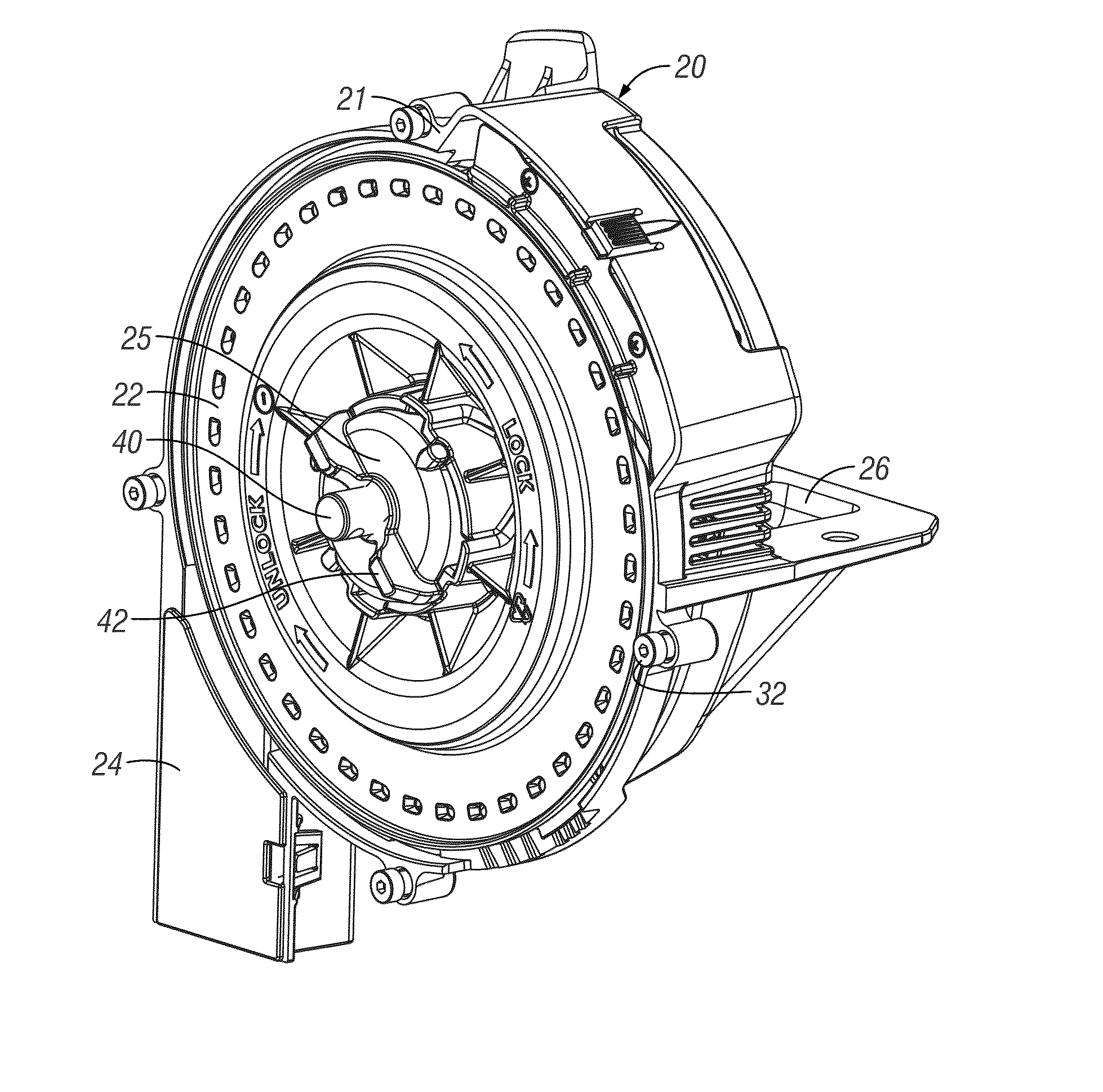
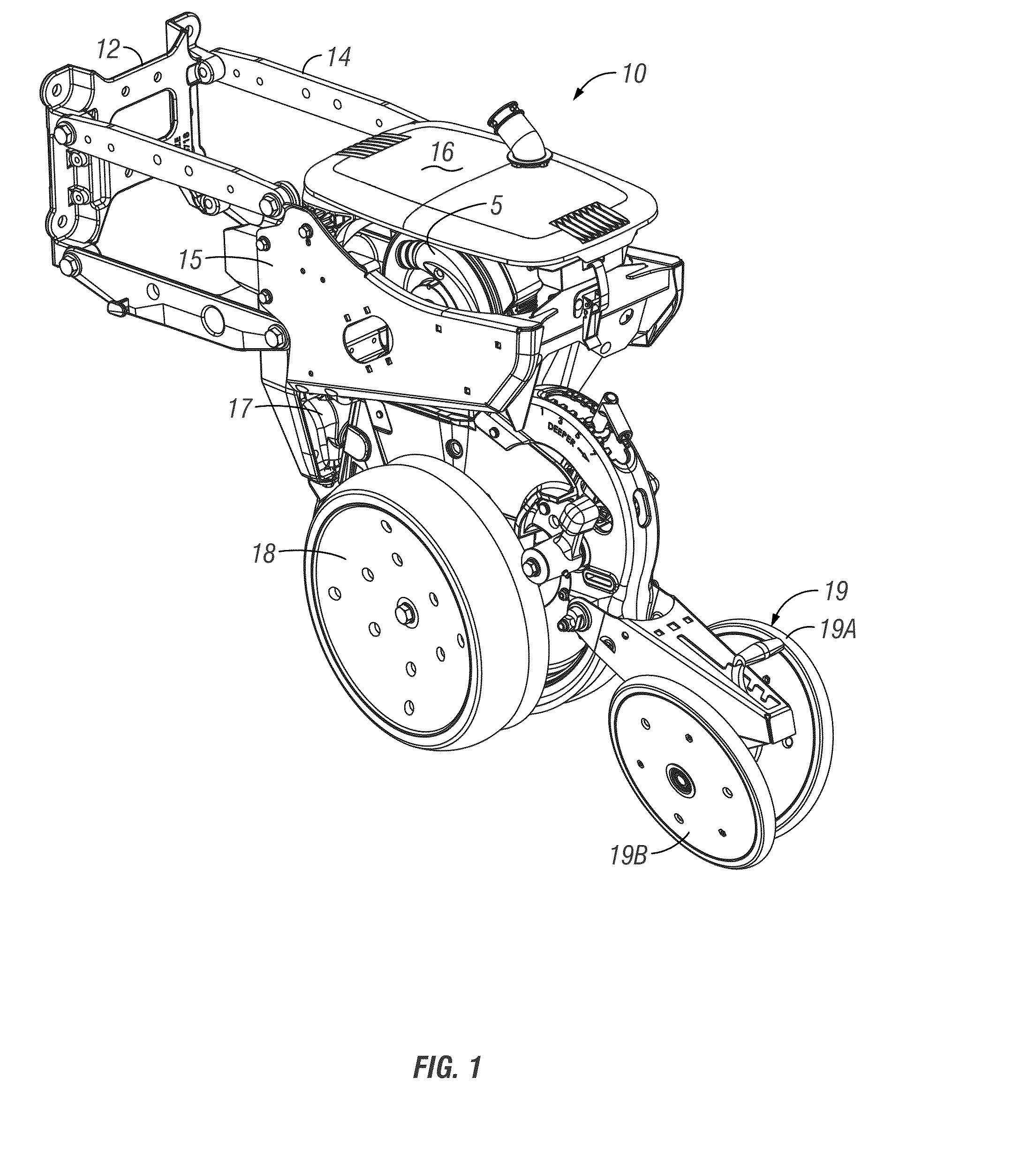
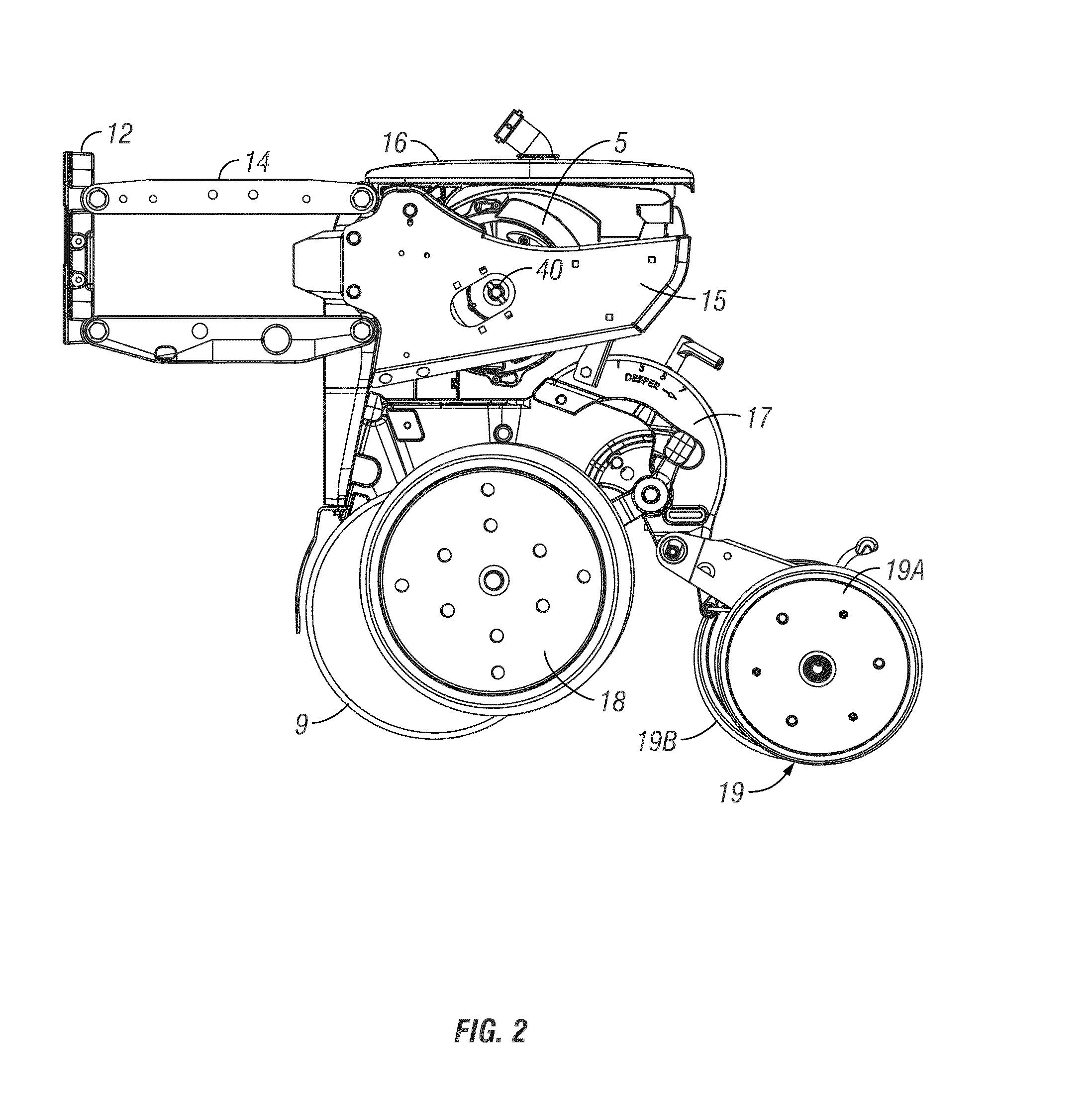
[0049]Referring to FIG. 1, a conventional planter row unit 10 with an air seed meter 5 is shown. The row unit 10 and air seed meter 5, as shown in FIGS. 1 and 2, is known in its general aspects to persons skilled in the art. The row unit 10 includes a U-bolt mount 11 for mounting the row unit 10 to a planter frame or tool bar (not shown), as it is sometimes called, which may be a steel tube of 5 by 7 inches (although other sizes are used). The mount 11 includes a faceplate 12, which is used to mount left and right parallel linkages. Each linkage may be a four-bar linkage, such as the left one 14 shown in FIG. 1. It is noted that the opposite (right) linkage is generally a mirror image of the linkage 14 shown in FIG. 1. The double linkage is sometimes described as having upper parallel links and lower parallel links, and the rear ends of all four parallel links are pivotally mounted to the frame 15 of the row unit 10. The frame 15 includes a support for an air seed meter 5 and seed h...


PUM


Abstract

A seed metering system, for use on a row crop planter, selects individual seeds from a seed reservoir and dispenses the seeds singularly at a controlled rate. A direct drive seed metering system includes a seed disc having a plurality of suction apertures with a recessed pocket adjacent to an aperture. The recessed pockets act to agitate seeds in the seed reservoir and to direct seed flow towards the apertures. A seed path relief system provides for allowing the placement of the seeds such that they are released from an outer edge of the seed disc. An adjustable seed singulator is mounted adjacent to the face of the seed disc where inner and outer blades are adjusted radially to compensate for the singulation of various seed sizes and shapes. The seed disc is driven via engagement of an internal gear with the external gear of an independent drive motor.

Description

CROSS-REFERENCE TO RELATED APPLICATIONS[0001]This application claims priority under 35 U.S.C. §119 to provisional patent application Ser. No. 61 / 717,384, filed Oct. 23, 2012, and which is hereby incorporated in its entirety.FIELD OF THE INVENTION[0002]The present invention relates generally to mechanisms used in agricultural planting machines for selecting and dispensing individual seeds. More particularly, but not exclusively, the invention relates to air seed meters used to meter seeds from a row unit on agricultural row crop planters and seeders.BACKGROUND OF THE INVENTION[0003]An agricultural row crop planter is a machine built for precisely distributing seed into the ground. The row crop planter generally includes a horizontal toolbar fixed to a hitch assembly for towing behind a tractor. Row units are mounted to the toolbar. In different configurations, seed may be stored at individual hoppers on each row unit, or it may be maintained in a central hopper and delivered to the r...

Claims


Application Information

Patent Timeline
Patent Type & Authority Applications(United States)
IPC IPC(8): A01C7/04
CPCA01C7/046A01C19/02Y02P60/00A01C7/04A01C7/042A01C7/044A01C7/125A01C7/102A01C7/128A01C7/124A01C7/08A01C7/121
Inventor WILHELMI, MATTHEW J.BROCKMANN, KALE J.
Owner KINZE MFG INC
Why Eureka
Try Eureka