
Modulating intensity of radiation beam

a radiation beam and intensity technology, applied in the field of radiation therapy and irradiation systems, can solve the problems of simple modulators, insufficient quality of external source radiation therapy, undesirable irradiation of tumorous tissue along with significant volume of oar in the path of radiation beam,

Inactive Publication Date: 2014-04-24
EIN GAL MOSHE
View PDF7 Cites 7 Cited by
  • Summary
  • Abstract
  • Description
  • Claims
  • Application Information

AI Technical Summary

Benefits of technology

The present invention provides a new device and method for adjusting the intensity of a radiation beam in a radiation field by using movable leaves that attenuate parts of the beam. The leaves are attached to radiolucent members, which are driven by a driver to move in directions perpendicular to the beam. The leaves' movements are determined by motion profiles that are derived from an attenuation map. The invention can be used in a radiation system that emits a beam in a radiation field and can be adjusted to different target positions and orientations. The invention allows for precise control over the radiation beam and can be used in various radiation treatment applications.

Problems solved by technology

However, external-source radiation therapy undesirably irradiates a significant volume of OAR in the path of the radiation beam along with the tumorous tissue.
Since separate irradiation of each beamlet is cumbersome, beamlets are grouped into field segments incorporating respectively uniform segment intensities.
Simple modulators, e.g., a wedge, do not generally provide on their own IMRT with sufficient quality.

Method used


Image

  • Modulating intensity of radiation beam
  • Modulating intensity of radiation beam
  • Modulating intensity of radiation beam

Examples


Embodiment Construction

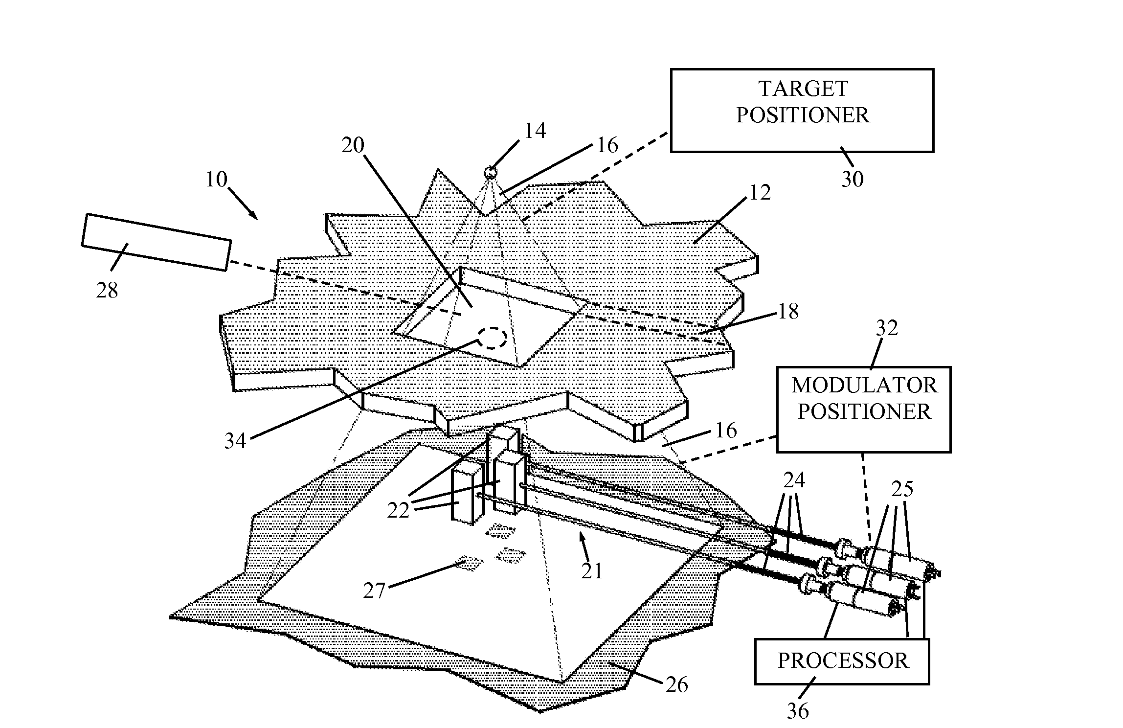
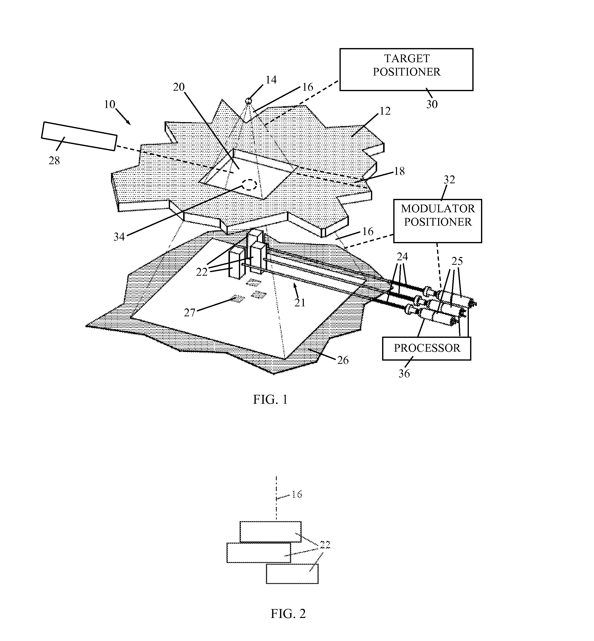
[0026]Reference is now made to FIG. 1, which illustrates a radiation system 10 with a collimator system 12 (or for short, collimator 12), constructed and operative in accordance with a non-limiting embodiment of the present invention.

[0027]In the non-limiting illustrated embodiment, radiation system 10 (e.g., a LINAC) includes a radiation source 14 that emits a radiation beam 16. The radiation source 14 and collimator 12 can be positioned in a gantry (not shown), as is well known in the art. Any radiation may be used, such as but not limited to, electron radiation or photon radiation (gamma radiation). As is known in the art, during treatment, beam 16 is trained on a target typically surrounding the isocenter of the gantry rotation. Imaging apparatus (not shown), such as a fluoroscope or ultrasound apparatus, for example, may be provided for imaging the target irradiated by radiation beam 16. The imaging apparatus may be used in conjunction with a closed loop, feedback control syste...


PUM


Abstract

A modulator for use in a radiation system with directional radiation beams respectively collimated into radiation fields, including a plurality of displaceable radiation attenuating elements arranged in at least one row, the radiation attenuating elements being configured to attenuate portions of a radiation beam inside the radiation field according the position of the radiation attenuating elements, and wherein each radiation attenuating element is respectively attached to a substantially radiolucent member, and a driver operable to store motion profiles and to respectively drive the radiation attenuating elements in directions generally perpendicular to the radiation beam via the substantially radiolucent members, wherein the respective motions of the radiation attenuating elements are according to corresponding motion profiles, and wherein a motion profile relates position and / or velocity of the radiation attenuating elements to time and / or irradiation level.

Description

FIELD OF THE INVENTION[0001]The present invention relates generally to radiotherapy and irradiation systems, and particularly to modulating the intensity of a radiation beam by one or more attenuating leaves positioned in a radiation field.BACKGROUND OF THE INVENTION[0002]Medical equipment for radiation therapy treats tumorous tissue with high energy radiation. The dose and the placement of the dose must be accurately controlled to insure that the tumor receives sufficient radiation to be destroyed, and that damage to the surrounding and adjacent non-tumorous tissue, referred to as organs at risk (OAR), is minimized.[0003]Radiation therapy typically uses a radiation source that is external to the patient, typically either a radioisotope, such as cobalt-60, or a high energy x-ray source, such as a linear accelerator. The external source produces a collimated beam directed into the patient to the tumor site. However, external-source radiation therapy undesirably irradiates a significa...

Claims


Application Information

Patent Timeline
Patent Type & Authority Applications(United States)
IPC IPC(8): G21F3/00A61N5/10
CPCA61N5/1042A61N5/1081A61N2005/1095G21F3/00
Inventor EIN-GAL, MOSHE
Owner EIN GAL MOSHE
Learn More