Power management circuit and method thereof

a power management circuit and power management technology, applied in the direction of electric variable regulation, process and machine control, instruments, etc., can solve the problems of increasing the overall processing load and the operational power consumption of the rechargeable battery, the current existing portable electronic device may not have the mechanism for identifying the usb port or operating in responsive to different types of usb ports, and the charging efficiency may be lowered, so as to achieve convenient and stable operation of the portable electronic device. the effect of increasing

Active Publication Date: 2014-04-24
WISTRON CORP
View PDF10 Cites 37 Cited by
  • Summary
  • Abstract
  • Description
  • Claims
  • Application Information

AI Technical Summary

Benefits of technology

[0008]Accordingly, an exemplary embodiment of the present disclosure provides a power management circuit and method thereof. The power management circuit and method thereof can actively determine whether the portable electronic device can initiate the booting process and configure the initial system power consumption according to the type of the USB power supplying port and the supply power thereof. Consequently, the issues of instantly turning on and off causing instability of the portable electronic device due to the connected USB power supplying port not being compatible to the system power consumption required or the insufficient power provided by the built-in rechargeable battery may be avoided. The convenience and stability of the portable electronic device can therefore increase.
[0009]An exemplary embodiment of the present disclosure provides a power management circuit which can be adapted for a portable electronic device. The portable electronic device has a universal serial bus (USB) charging port and is electrically connected to a USB power supplying port through the USB charging port to receive a supply voltage. The power management circuit includes a USB detection unit, a voltage detection unit, and a control unit. The USB detection unit is coupled to the USB charging port and determines the type of the USB power supplying port connected to the USB charging port being a Standard Downstream Port (SDP) or a Dedicated Charging Port (DCP). The voltage detection unit is coupled to the USB charging port for detecting the supply voltage. The control unit is coupled to the USB detection unit and the voltage detection unit. The control unit configures a system power consumption of the portable electronic device based on the type of the USB power supplying port and the supply voltage. When the portable electronic device initiates the booting process with the USB power supplying port being the DCP and the supply voltage being lowered than a threshold, the control unit reduces the system power consumption of the portable electronic device to maintain the supply voltage above the threshold for the portable electronic device to boot normally.
[0010]An exemplary embodiment of the present disclosure provides a power management method adapted for a portable electronic device having a USB charging port. The portable electronic device further is electrically connected to a USB power supplying port through the USB charging port to receive a supply voltage. The power management method includes the following steps. Firstly, whether the USB power supplying port being a SDP port or a DCP port is determined. Subsequently, the supply voltage is detected. Then, a system power consumption of the portable electronic device is configured based on the type of the USB power supplying port and the supply voltage. When the portable electronic device initiates the booting process with the USB power supplying port being the DCP port and the supply voltage being lowered than a threshold, reduces the system power consumption of the portable electronic device to maintain the supply voltage above the threshold for the portable electronic device to boot normally.
[0011]To sum up, an exemplary embodiment of the present disclosure provides a power management circuit and method thereof. The power management circuit and method thereof can actively determine whether the portable electronic device is capable of initiating the booting process and configuring the initial system power consumption through detecting the type of the USB power supplying port and the supply power thereof at system prior to the initiation of the booting process. Consequently, the issues of instantly turning on and off effecting the stability of the portable electronic device owing to the connected USB power supplying port not being able to support the system power consumption required or the power provided by the built-in rechargeable battery being insufficient can be effectively avoided. Accordingly, the convenience and stability of the portable electronic device can be increased.

Problems solved by technology

Currently as more and more power consumed functionalities including Bluetooth, WiFi and 3 G communication have been incorporated in the portable electronic devices thereby increasing the overall processing loads and the operational power consumption of the rechargeable battery thereof.
However, the current existing portable electronic device may not have the mechanism for identifying the USB port or for operating in responsive to different type of the USB ports.
Accordingly, when a user uses the wrong type of the charging port to supply the operation power or to charge the rechargeable battery, not only the charging efficiency may be lowered, but also could cause the instability of the system.
In particular, when the portable electronic device has booting the system using the power received from improper USB port, the system could face overloading issue resulting from insufficient supply power and constantly switching on and off eventually leading to malfunction of the system.
Consequently, the portable electronic device may thus experience instantly turning on and off due to insufficient power and eventually lead to the malfunction of the portable electronic device.

Method used


Image

  • Power management circuit and method thereof
  • Power management circuit and method thereof
  • Power management circuit and method thereof

Examples


first exemplary embodiment

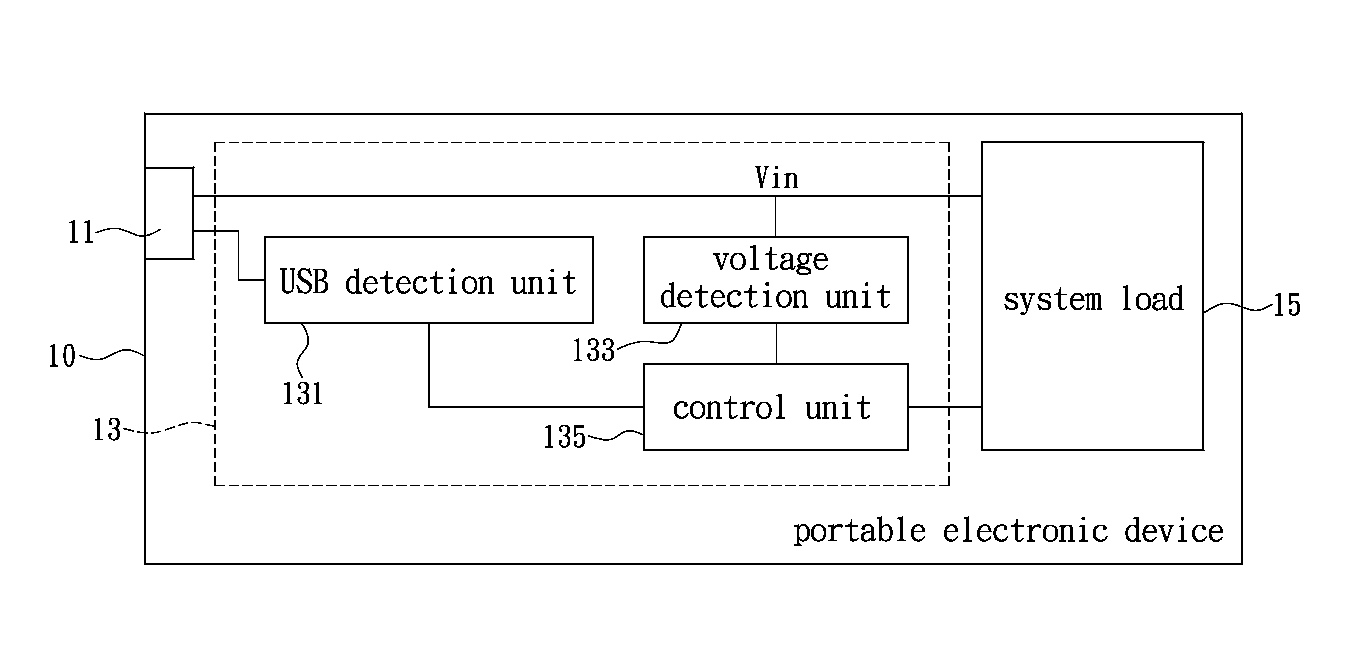
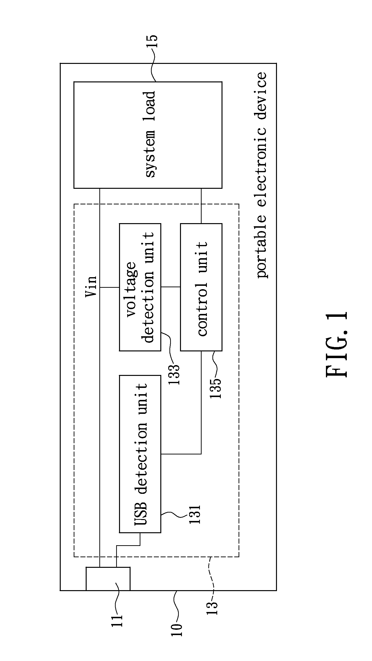
[0022]Please refer to FIG. 1 which shows a block diagram illustrating a portable electronic device provided in accordance to the first exemplary embodiment of the present disclosure. The portable electronic device 10 may be a portable electronic device having a universal serial bus (USB) port including but not limited to a smart phone, a tablet, a personal digital assistance (PDA), a laptop, a digital camera, and an MP3 player.

[0023]The portable electronic device 10 includes a USB charging port 11, a power management circuit 13, and a system load 15. Simply speaking, the portable electronic device 10 can electrically connect to an external USB power supplying port (not shown) through the built-in USB charging port 11 to receive a supply voltage Vin. The power management circuit 13 can actively determines a supply power of the USB power supplying port and correspondingly configures the operation of the system load 15 according to the detected type of the USB power supplying port and ...

second exemplary embodiment

[0052]Please refer to FIG. 4, which shows a schematic diagram illustrating the portable electronic device provided in accordance to a second exemplary embodiment of the present disclosure. In the instant embodiment, the portable electronic device 20 may be a portable electronic device having a universal serial bus (USB) port including but not limited to a smart phone, a tablet, a personal digital assistance (PDA), a laptop, a digital camera, and an MP3 player.

[0053]The portable electronic device 20 includes a USB charging port 21, a power management 23, and a system load 25. The portable electronic device 20 can electrically connect to an external USB power supplying port (not shown) through the built-in USB charging port 21 to receive a supply voltage Vin. The power management circuit 23 can actively drive the operation of the system load 25 according to the type and supplied power associated with the USB power supplying port. The system load 25 in the instant embodiment may repres...

third exemplary embodiment

The Third Exemplary Embodiment

[0063]The power management circuit 33 may include a voltage conversion unit to accept various input voltage with various voltage level. Please refer FIG. 5, which shows a block diagram illustrating a portable electronic device provided in accordance to a third exemplary embodiment of the present disclosure. In the instant embodiment, the portable electronic device 30 may be a portable electronic device having a universal serial bus (USB) port including but not limited to a smart phone, a tablet, a personal digital assistance (PDA), a laptop, a digital camera, and an MP3 player.

[0064]The portable electronic device 30 includes a USB charging port 31, a power management 33, and a system load 35. The portable electronic device 30 can electrically connect to an external USB power supplying port (not shown) through the built-in USB charging port 31 to receive a supply voltage Vin. The power management circuit 33 can drive the operation of the system load 35 a...


PUM


Abstract

A power management circuit adapted for a portable electronic device is provided. The portable electronic device receives a supply voltage from a USB power supplying port through a built-in USB charging port. The power management circuit includes a USB detection unit, a voltage detection unit, and a control unit. The USB detection unit determines the type of the USB power supplying port. The voltage detection unit detects the supply voltage. The control unit configures the power consumption of the portable electronic device based on the type of the USB power supplying port and the supply voltage. When the portable electronic device initiates booting process with the USB power supplying port being the Dedication Charging Port and the supply voltage being lowered than a threshold, the control unit reduces the power consumption of the portable electronic device to maintain the supply voltage above the threshold for booting stably.

Description

BACKGROUND[0001]1. Technical Field[0002]The present disclosure relates to a power management circuit and a method thereof, in particular, to a power management circuit and a method thereof for a portable electronic device having at least a USB charging port.[0003]2. Description of Related Art[0004]As technology advanced, portable electronic electronics such as smart phone, tablet, laptop, digital camera, video camcorder and MP3 player have been widely used in our daily life. Portable electronic devices are often equipped with rechargeable batteries supplying the required power for the carrying convenience of users. Currently as more and more power consumed functionalities including Bluetooth, WiFi and 3 G communication have been incorporated in the portable electronic devices thereby increasing the overall processing loads and the operational power consumption of the rechargeable battery thereof. Accordingly, fast charging has become a desirable objective to achieve for users of the...

Claims


Application Information

Patent Timeline
Patent Type & Authority Applications(United States)
IPC IPC(8): G05F1/10
CPCG05F1/10G06F1/305
Inventor CHOU, YING-TZULEE, CHUN-TAKUNG, CHIH CHAINSHEU, CHIA ZENLIU, TSANG PING
Owner WISTRON CORP
Why Eureka
Try Eureka