Systems and Methods for Imaging Using a Random Laser

a random laser and imaging technology, applied in the field of imaging, can solve the problems of spatial coherence leading to coherent imaging artifacts, poor suited lasers and slds for full-field imaging applications, and corrupting images, so as to achieve lower coherence illumination, reduce coherence, and reduce coherence. effect of illumination

Active Publication Date: 2014-04-24
YALE UNIV
View PDF4 Cites 13 Cited by
  • Summary
  • Abstract
  • Description
  • Claims
  • Application Information

AI Technical Summary

Problems solved by technology

Despite their brightness, lasers and SLDs are poorly suited for full-field imaging applications because their higher spatial coherence leads to coherent artifacts such as speckle that corrupt image formation.
On the other hand, spatial coherence leads to coherent imaging artifacts.
Coherent artifacts originate from interference that occurs during image formation.
The resulting intensity modulations appear as additional features that are not present in the object, thereby corrupting the image.
However, the most common manifestation of coherent artifacts is speckle, which occurs when a rough object or scattering environment introduces random phase delays among mutually coherent photons which interfere at the detector.
Speckle is a long-standing issue because it impairs image interpretation by a human observer.
From this perspective, the limitations of thermal sources and conventional lasers are clear.
On the other hand, conventional lasers have many photons per coherence volume (high photon degeneracy) but readily generate coherent artifacts (high spatial coherence).
This field relating to random lasers is relatively young and as such does not have many realized applications.
To date, complex lasers have not been adopted or applied in an imaging context.
Spatial coherence of random laser emission, however, is not well understood despite initial observations indicating that it is much lower than in a conventional laser.

Method used


Image

  • Systems and Methods for Imaging Using a Random Laser
  • Systems and Methods for Imaging Using a Random Laser
  • Systems and Methods for Imaging Using a Random Laser

Examples


Embodiment Construction

)

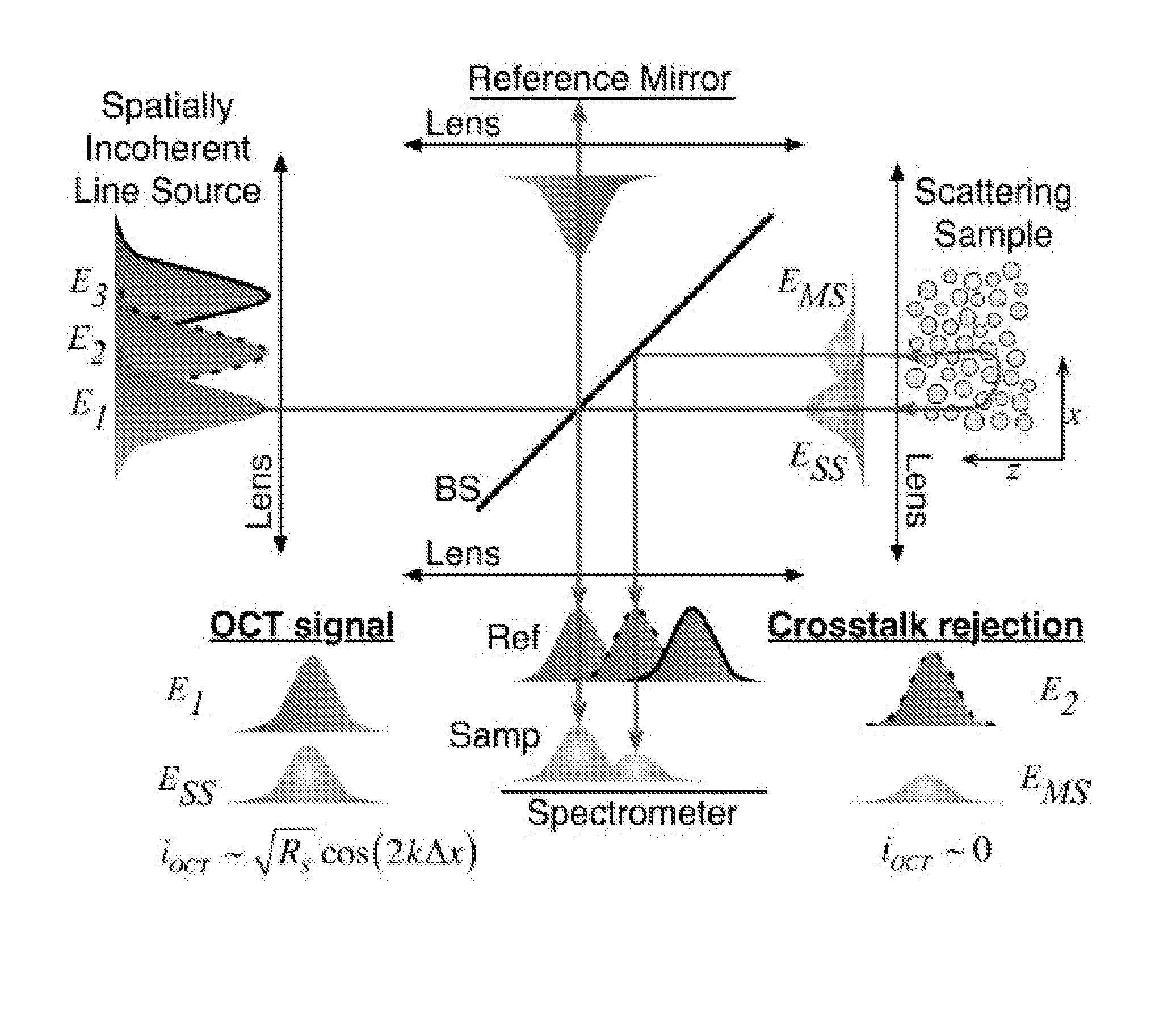
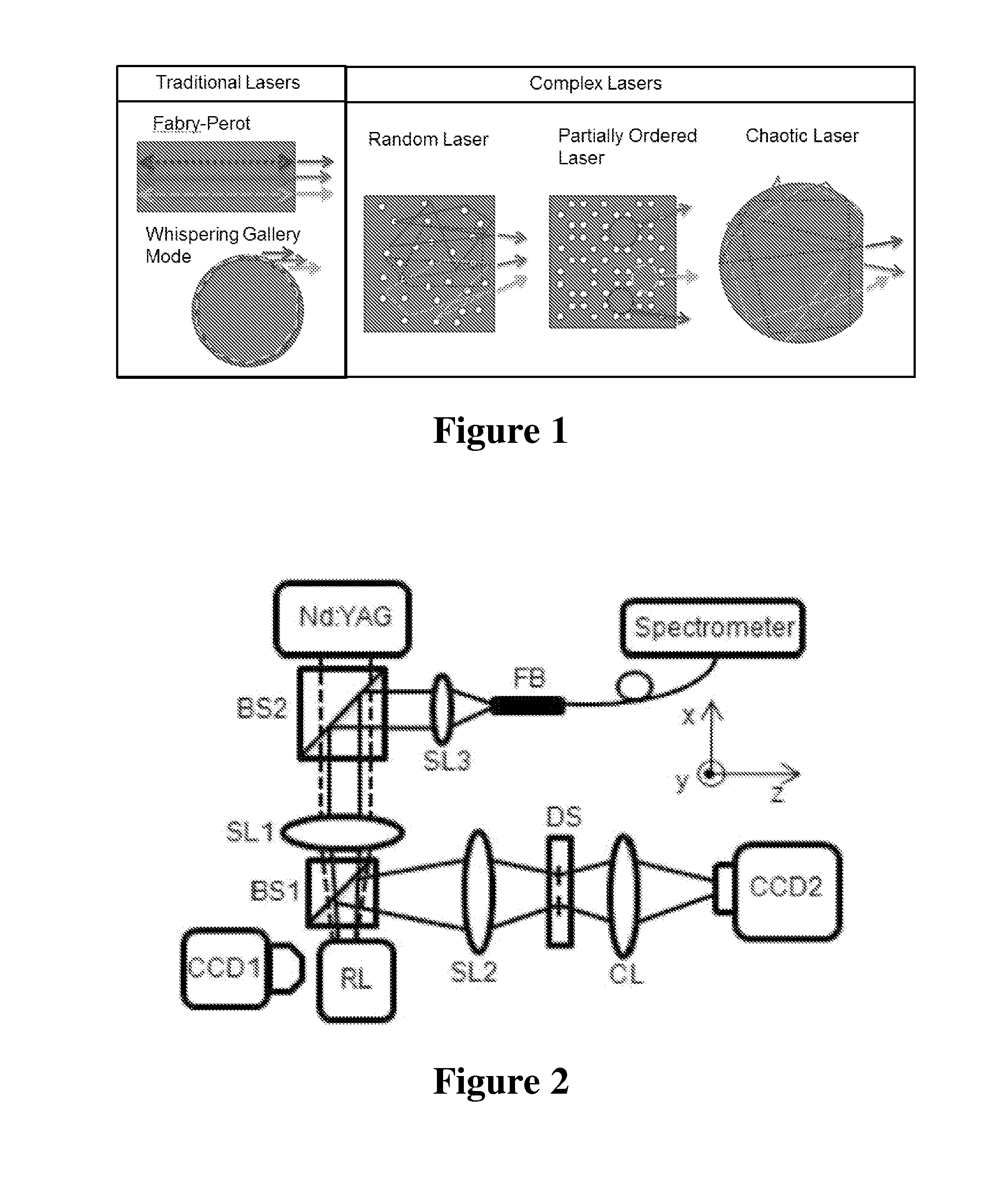
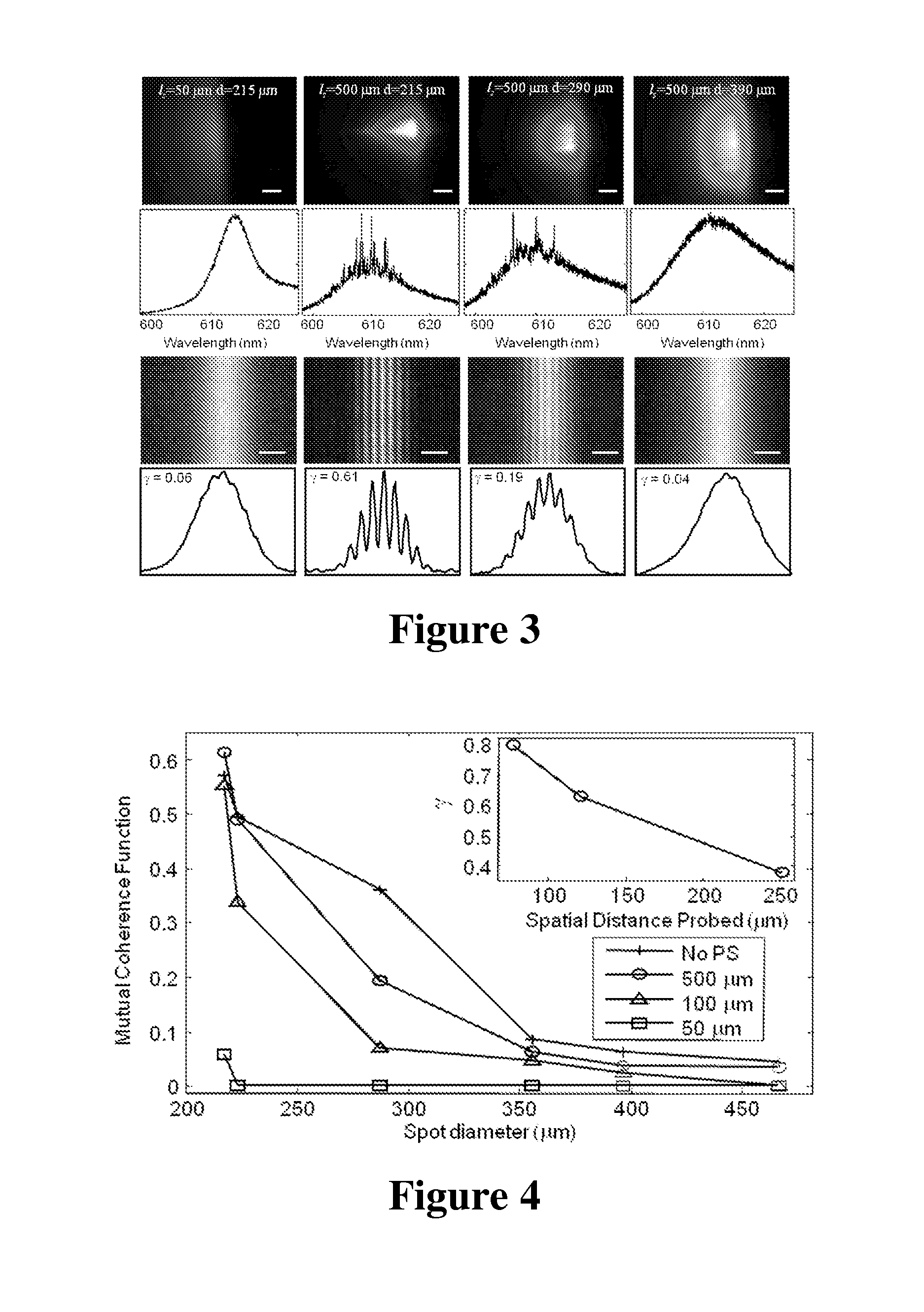
[0030]According to the present disclosure, advantageous systems and methods are provided for imaging using complex lasers. In general, a complex laser may by used as an electromagnetic source for an imaging application (e.g., visible light, ultraviolet radiation, near infrared radiation, infrared radiation, microwaves, x-rays, etc.). The use of a lower spatial coherence configured complex laser in imaging applications may advantageously mitigate coherent artifacts in imaging such as cross-talk and speckle and improve overall image quality. Exemplary imaging applications where a complex laser may be useful include both incoherent imaging applications, such as digital light projectors and traditional microscopy, and coherent imaging applications, such as optical coherence tomography (OCT) and holography. A complex laser may also be applied to coherent ranging applications. As demonstrated herein, a lower spatial coherence configured complex laser may be particularly useful for imagin...


PUM


Abstract

Systems and methods are provided for imaging using complex lasers. In general, a complex laser may be used as an electromagnetic source for an imaging application. The use of a lower spatial coherence configured complex laser in imaging applications may advantageously mitigate coherent artifacts in imaging such as cross-talk and speckle and improve overall image quality. Imaging applications where a complex laser may be useful include both incoherent imaging applications, such as digital light projectors and traditional microscopy, and coherent imaging applications, such as optical coherence tomography (OCT) and holography. The systems and methods provided also enable controlling the degree of spatial coherence of a complex laser.

Description

STATEMENT OF GOVERNMENT SUPPORT[0001]The United States government may hold license and / or other rights in this invention as a result of financial support provided by governmental agencies in the development of aspects of the invention. Parts of this work were supported by the government under DMR-0803987. Parts of this work were also supported by the government under NSF Grants ECCS-1128542 and ECCS-1068642. Parts of this work were also supported by the government under K12 award through the Yale Child Health Research Center (5K12-HD001401-12).CROSS-REFERENCE TO RELATED APPLICATIONS[0002]The present application is related to and claims priority benefit to a co-pending, commonly assigned provisional patent application entitled “Spatially incoherent random laser emission for speckle-free and cross-talk free illumination,” which was filed on Apr. 14, 2011, and assigned Ser. No. 61 / 475,354. The present application also is related to and claims priority benefit to a co-pending, commonly ...

Claims


Application Information

Patent Timeline
Patent Type & Authority Applications(United States)
IPC IPC(8): H04N5/235H01S3/10
CPCH01S3/10H04N5/235G02B27/48H04N9/3161H01S5/041H01S5/10H01S3/0804H01S3/213H01S3/30H04N23/70
Inventor CAO, HUIREDDING, BRANDONCHOMA, MICHAEL
Owner YALE UNIV
Why Eureka
Try Eureka