Device supporting tracheal tube

Inactive Publication Date: 2014-04-24
DE DOMENICO ANDREA
View PDF7 Cites 8 Cited by
  • Summary
  • Abstract
  • Description
  • Claims
  • Application Information

AI Technical Summary

Benefits of technology

[0020]Another significant feature of the present invention is the possibility of integration in a guiding system by magnetic means, according to concepts and disclosure from the European patent application EP 11425045 (De Domenico), so that the intubation procedure can be adapted to different operative circumstances, especially in the case where a direct or indirect visual perception of the situation is possible. More specifically, the above integration would achieve a synergy of the two systems, the first based on planar elements and the second based on magnetic elements

Problems solved by technology

Despite the improvement of such technique, obtained at a global level by years of clinical practice, and despite the different shapes of laryngoscopic blades that have been designed and are available on the market, in some cases, direct laryngoscopy remains impossible, either because of particular anatomical parts in a given person or because of particular situations that can happen in an emergency.
For example, direct laryngoscopy is not possible when the alignment of the patient's three axes (oral axis, pharyngeal axis and laryngeal axis) can

Method used


Image

  • Device supporting tracheal tube
  • Device supporting tracheal tube
  • Device supporting tracheal tube

Examples


Embodiment Construction

[0042]It is here underlined that only a few of the many conceivable embodiments of the present invention are described, which are just some specific non-limiting examples, having the possibility to describe many other embodiments based on the disclosed technical solutions of the present invention.

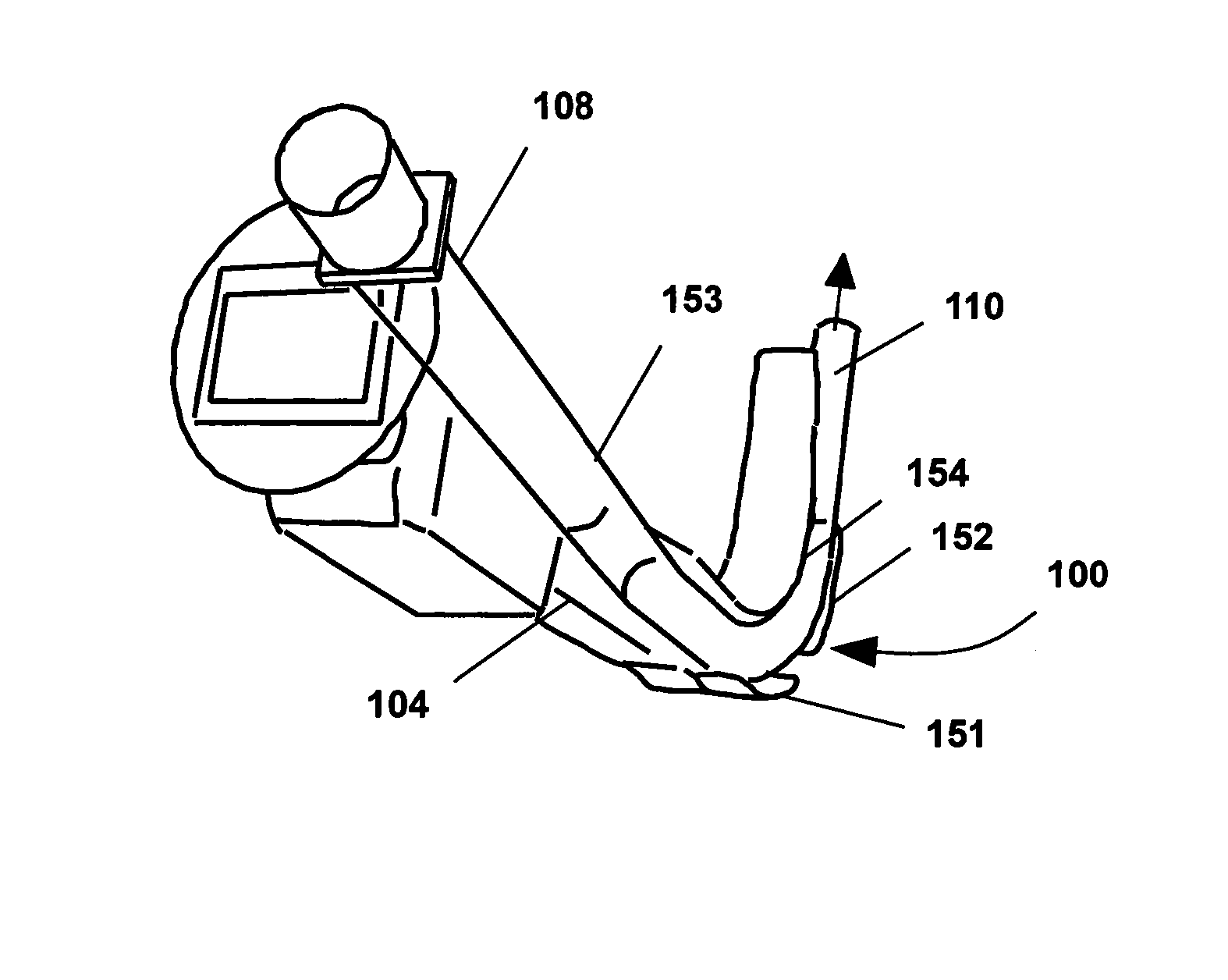
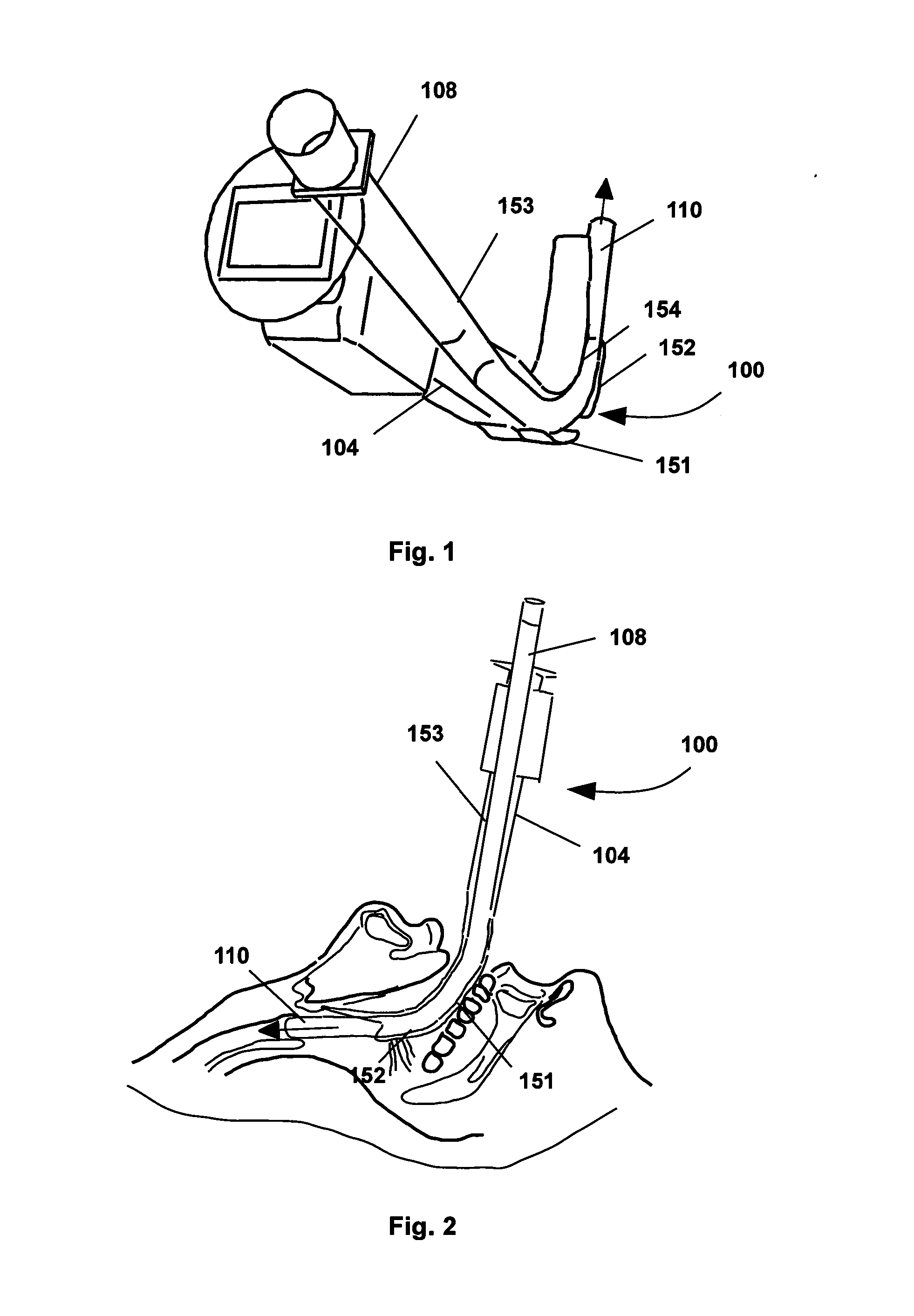
[0043]In FIG. 1 is illustrated a Airtraq® videolaryngoscope 100, particularly suitable as a support to the procedure of tracheal intubation of a patient. The blade 104, of the same videolaryngoscope 100, in the prior art has a longitudinal profile with some fixed protruding walls 151, 152, 154, that achieve a guiding and routing tunnel, along which an endotracheal tube 108 is inserted up to its final position, with the distal end in the trachea, as illustrated in FIG. 2.

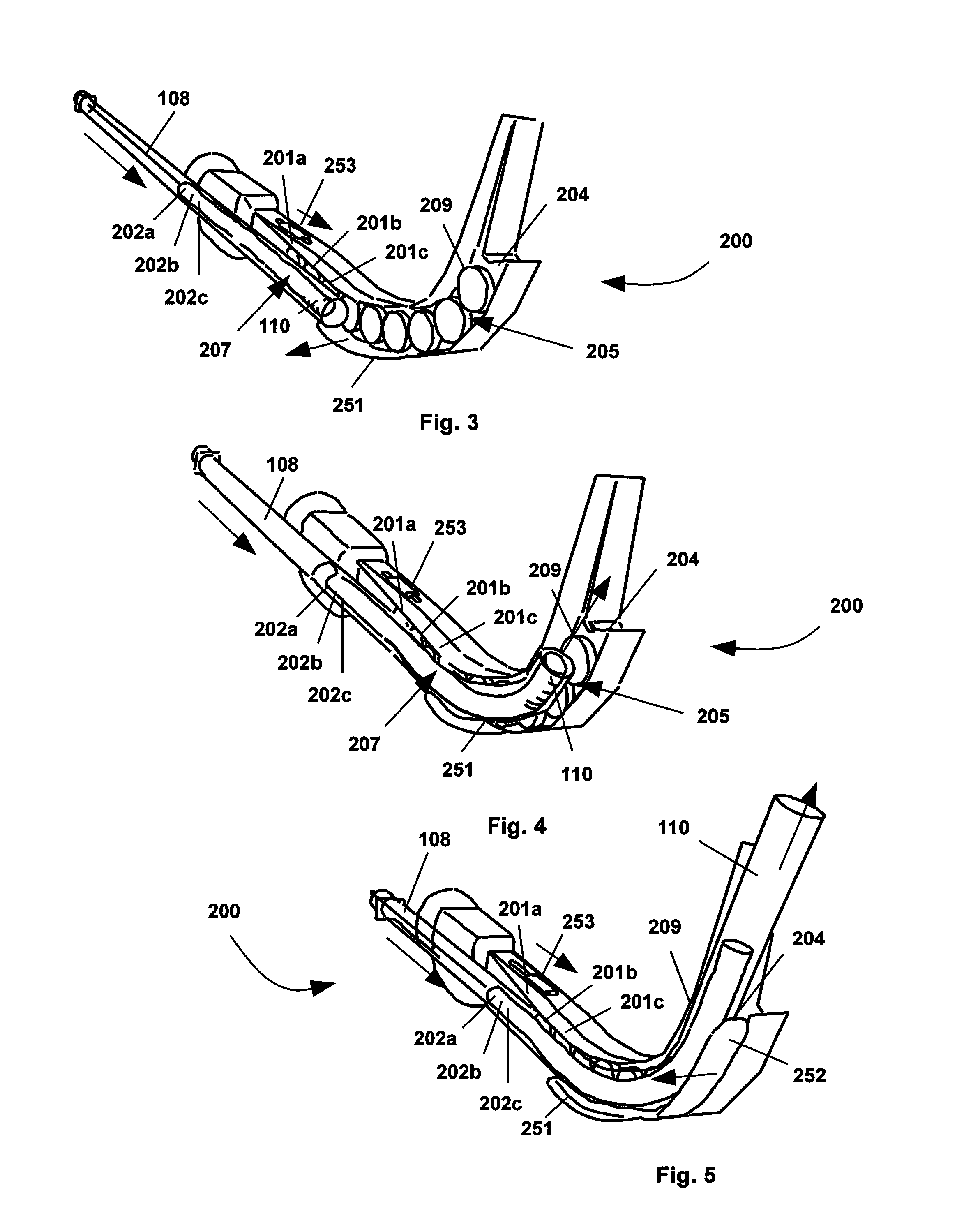
[0044]Instead, device 100 of the present invention is characterized by having the protruding walls partially or completely removed. More exactly, the upper wall 154 has been partially removed, so that it can still push the u...


PUM


Abstract

A device for supporting a tracheal tube during tracheal intubation. The device is applied to the blade of a laryngoscope, or similar instrument. It includes one or more planar elements, each element having a profile adapted to the curvature of the blade a the location in which it is placed. On command, each element protrudes out from the blade through a longitudinal groove, in order to create one or more fixed transversal walls. Once the walls are created, the tracheal tube is then inserted into the laryngoscope and its far end is moved across the walls, and towards the trachea of the patient. The device also includes a set of mechanical gears that are controlled by a sliding button such that moving the button from a back position to a front position moves each of the planar elements from the position within the blade to the protruding position.

Description

CROSS-REFERENCE TO RELATED APPLICATIONS[0001]This patent application is a national phase entry under 35 U.S.C. §371 of PCT International Patent Application PCT / EP2012 / 0061135, filed Jun. 12, 2012, designating the United States and published in English as International Patent Publication WO 2012 / 171926 A1 on Dec. 20, 2012, which claims the benefit, under Article 8 of the PCT, of European Patent Application Serial No. 11425158.0, filed Jun. 14, 2011, the benefit and entire disclosure of each of which is hereby incorporated herein by this reference.FIELD OF THE INVENTION[0002]The present invention concerns a medical device, preferably applied to the blade of a laryngoscope, or an Airtraq® videolaryngoscope, or a LMA® videolaryngoscope, or other similar instrument, and particularly suitable as a support to the procedure of tracheal intubation of a patient. In particular, the device includes one or more planar elements, each having a profile that is perfectly adapted to the curvature of ...

Claims


Application Information

Patent Timeline
IPC IPC(8): A61M16/04A61B1/04A61B1/00A61B1/267
CPCA61M16/0488A61B1/267A61B1/04A61B1/00158A61B1/00131
Inventor DE DOMENICO, ANDREA
Owner DE DOMENICO ANDREA
Why Eureka
Try Eureka