Transformer provided with a taps panel, an electric-insulation method taps panel of a dry distribution transformer, and a taps panel for a dry distribution transformer

a technology of electric insulation and transformer, which is applied in the direction of reradiation, instruments, magnetic bodies, etc., can solve the problems of unprotected taps, unprotected taps, and unprotected taps

Active Publication Date: 2014-05-01
SIEMENS ENERGY GLOBAL GMBH & CO KG
View PDF2 Cites 14 Cited by
  • Summary
  • Abstract
  • Description
  • Claims
  • Application Information

AI Technical Summary

Benefits of technology

[0017]An objective of the present invention is to provide a transformer having a hermetically sealed compartment, which comprises a taps panel insulated by a removable solid resin, electrostatically shielded and that enables the change of taps on shielded coils, thus enabling their use on submersible dry transformers.

Problems solved by technology

Resin is applied by means of vacuum, and the taps panel remains on the outer part of the transformer, without any protection.
The disadvantage of these embodiments is the fact that the taps panel is unprotected, since dry distribution transformers are used in internal and protected environments.
However, the taps remain unprotected, without insulation in immersion condition, that is, the taps panel does not have a configuration suitable for used in such environments.
The disadvantage of these embodiments is the fact that the transformer uses the cover to protect the taps panel from moisture and water.
However, this cover only prevents accumulation of dust and has a low degree of electric insulation, so that the air present inside the protrusion may cause an electric discharge because it is ionized, thus damaging the transformer.
The disadvantage of this embodiment is that fact that the transformer uses a liquid dielectric material, as known from the prior art, liquid dielectric materials are very complex to handle, besides the possibility of being contaminated in case of maintenance, if the operator comes in contact with the material.
Another disadvantage of the liquid dielectric material is the fact that the latter may cause damages to the environment, if it is not discarded correctly.
A further problem of this embodiment is the fact that the operator has to make a ground connection to the grounded step of the transformer.

Method used


Image

  • Transformer provided with a taps panel, an electric-insulation method taps panel of a dry distribution transformer, and a taps panel for a dry distribution transformer
  • Transformer provided with a taps panel, an electric-insulation method taps panel of a dry distribution transformer, and a taps panel for a dry distribution transformer
  • Transformer provided with a taps panel, an electric-insulation method taps panel of a dry distribution transformer, and a taps panel for a dry distribution transformer

Examples


Embodiment Construction

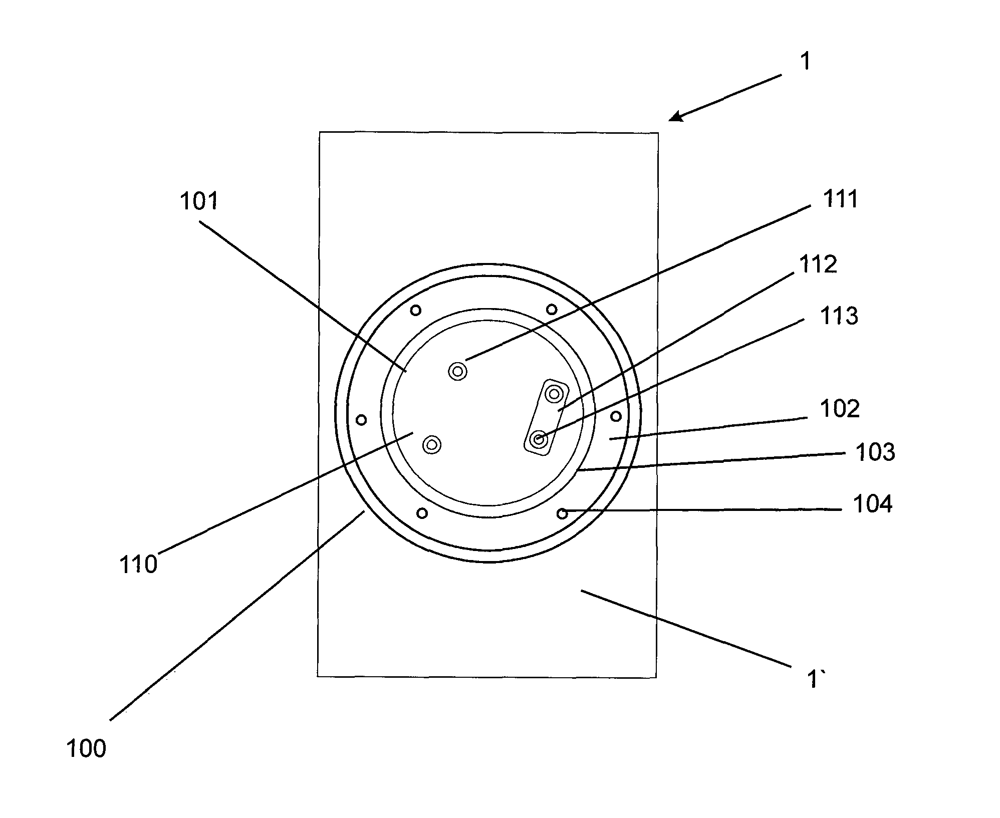
[0045]As one can see in FIGS. 6 to 9, the transformer 1 has a housing 1′, manufacture preferably from resin and consisting of a coil 200 encapsulated in resin and shielded electrostatically 107. Close to the outer wall of the transformer, a taps panel 110 is positioned inside a sealed compartment 100.

[0046]Said sealed compartment 100 is embodied as a protrusion that begins at the housing 1′ of the transformer 1 and forms an outer wall 105 and an inner wall 106.

[0047]The inner wall 106 forms a cavity 101 inside the sealed compartment 100, in which a fixation plate 102 and a cover 120 are inserted, the latter being recessed from the end portion 116 of the outer wall 105.

[0048]This recess has the objective of preventing accumulation of dirt and the entry of water in the cavity 101, this embodiment being particularly advantageous, since dirt accumulates on the outer wall 105, resulting in a more secure operation during the change of the taps, and this prevents the entry of dirt and the ...


PUM

PropertyMeasurementUnit
voltageaaaaaaaaaa
voltageaaaaaaaaaa
voltageaaaaaaaaaa

Abstract

The present invention relates to a dry distribution transformer comprising a housing (1′), a coil (200), a sealed compartment (100) and a taps panel (1 10) associated to the coil (200). The taps panel (110) has an electrostatic shield (107) and is positioned inside the sealed compartment (100), the sealed compartment (100) being filled with a solid dielectric material and protected by a cover (120). One also describes an electric insulation method for a taps panel of a dry distribution transformer and taps panel for a dry distribution transformer filled with removable insulating resin. The coil (200) has a grounded (115) electrostatic shield (107).

Description

[0001]This application claims priority of Brazilian Patent Application PI1101495-4, filed on Apr. 15, 2011, the contents being hereby incorporated by reference.[0002]The present invention relates to a taps panel for a three-phase or single-phase electric transformer, of solid insulation and with shielded and grounded coils, particularly designed for use at underground or submerged distribution installation, or internal or external installation.DESCRIPTION OF THE PRIOR ART[0003]As known from the prior art, transformers are widely employed for transforming electric energy. Transmission of electric energy is carried out at high voltage as far as close to the consumption places, where, also by means of transformers, it is reduced to values suitable for the pieces of equipment of the consumers. Voltage-level reduction may be made by means of taps, which are essentially connection points along a coil winding, which enables the selection of a given number of turn along the winding. In this...

Claims


Application Information

Patent Timeline
Patent Type & Authority Applications(United States)
IPC IPC(8): H01F29/02H01F41/00H01F27/36
CPCH01F29/025H01F27/362H01F41/005H01F2027/328Y10T29/4902H01F27/363H01F27/06H01F27/08H01F27/02H01F27/36
Inventor NAVARRO, MARTIN ALSINA
Owner SIEMENS ENERGY GLOBAL GMBH & CO KG
Why Eureka
Try Eureka