Device and method for extending dynamic range in an image sensor

Active Publication Date: 2014-05-01
PIXON IMAGING
View PDF3 Cites 17 Cited by
  • Summary
  • Abstract
  • Description
  • Claims
  • Application Information

AI Technical Summary

Benefits of technology

[0012]The present invention provides methods of extending the dynamic range of an image sensor as sensor noise starts to limit the low-light end of the sensor's dy

Problems solved by technology

Despite major improvements in solid-state image sensor and digital camera technology, conventional digital cameras may have a maximum photo-signal storage capacity that limits the dynamic range of the particular system.
The charge handling capacity is limited by the maximum voltage swing in the integrated circuitry and the storage capacitance within the pixel.
Once a maximum charge capacity is reached, the sensor no longer senses image brightness, resulting in data loss.
Two common problems faced by all cameras are scenes with wide dynamic range (WDR), and poor sensitivity in low-light situations.
Unfortunately, many outdoor and indoor scenes with highly varying illumination have a dynamic range significantly greater than 4,000:1.
Under even darker conditions, one may find that light is undetectable from portions of the image, i.e., image information is entirely lost.
High dynamic range imagery is a serious and frequent problem in surveillance and security video.
Consequently, there has been considerable effort expended on trying to solve this problem.
11-17)

Method used


Image

  • Device and method for extending dynamic range in an image sensor
  • Device and method for extending dynamic range in an image sensor
  • Device and method for extending dynamic range in an image sensor

Examples


Example

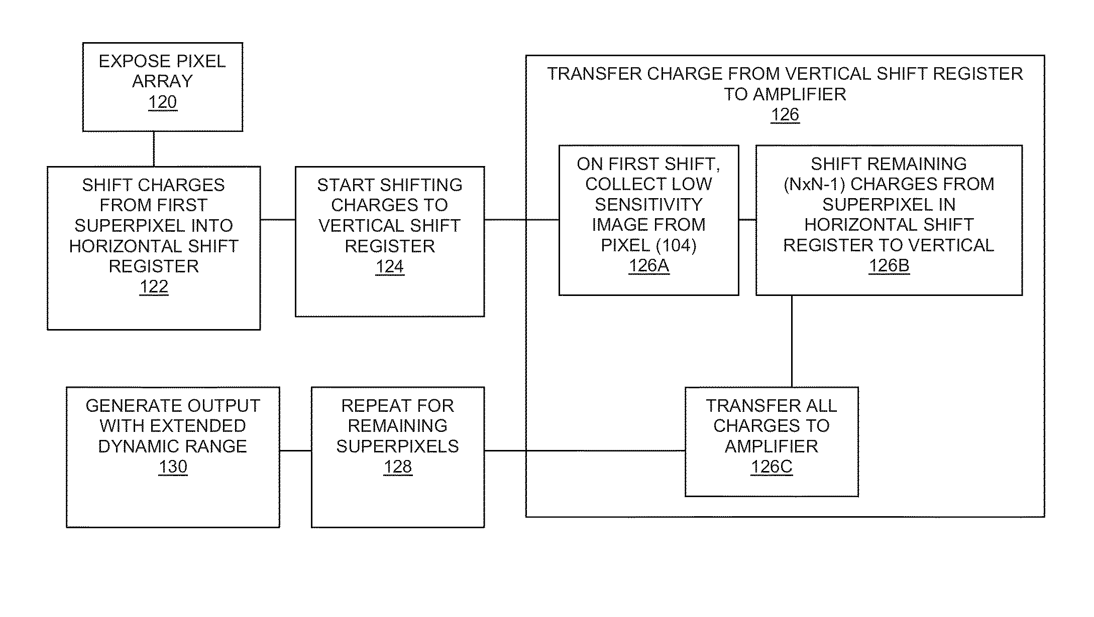
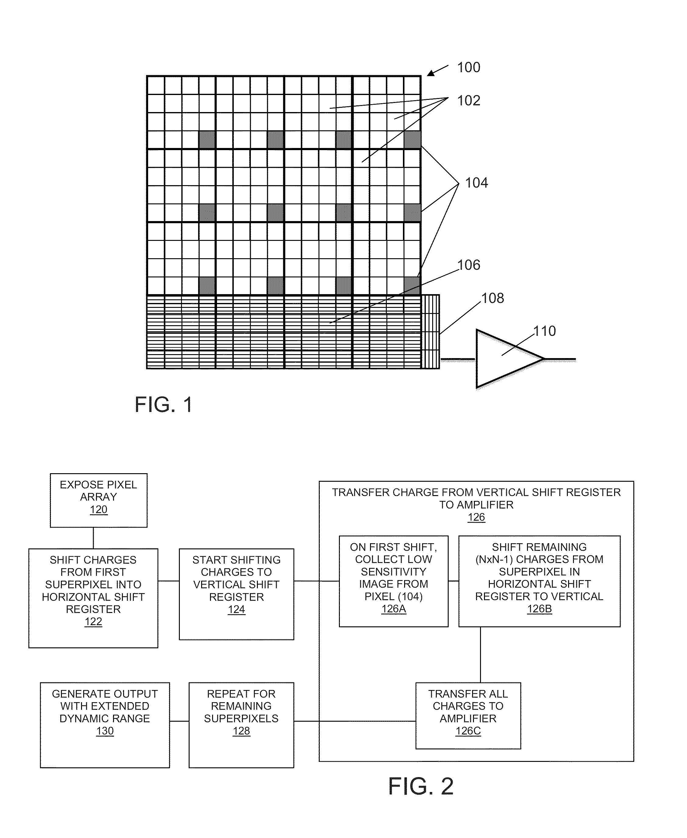
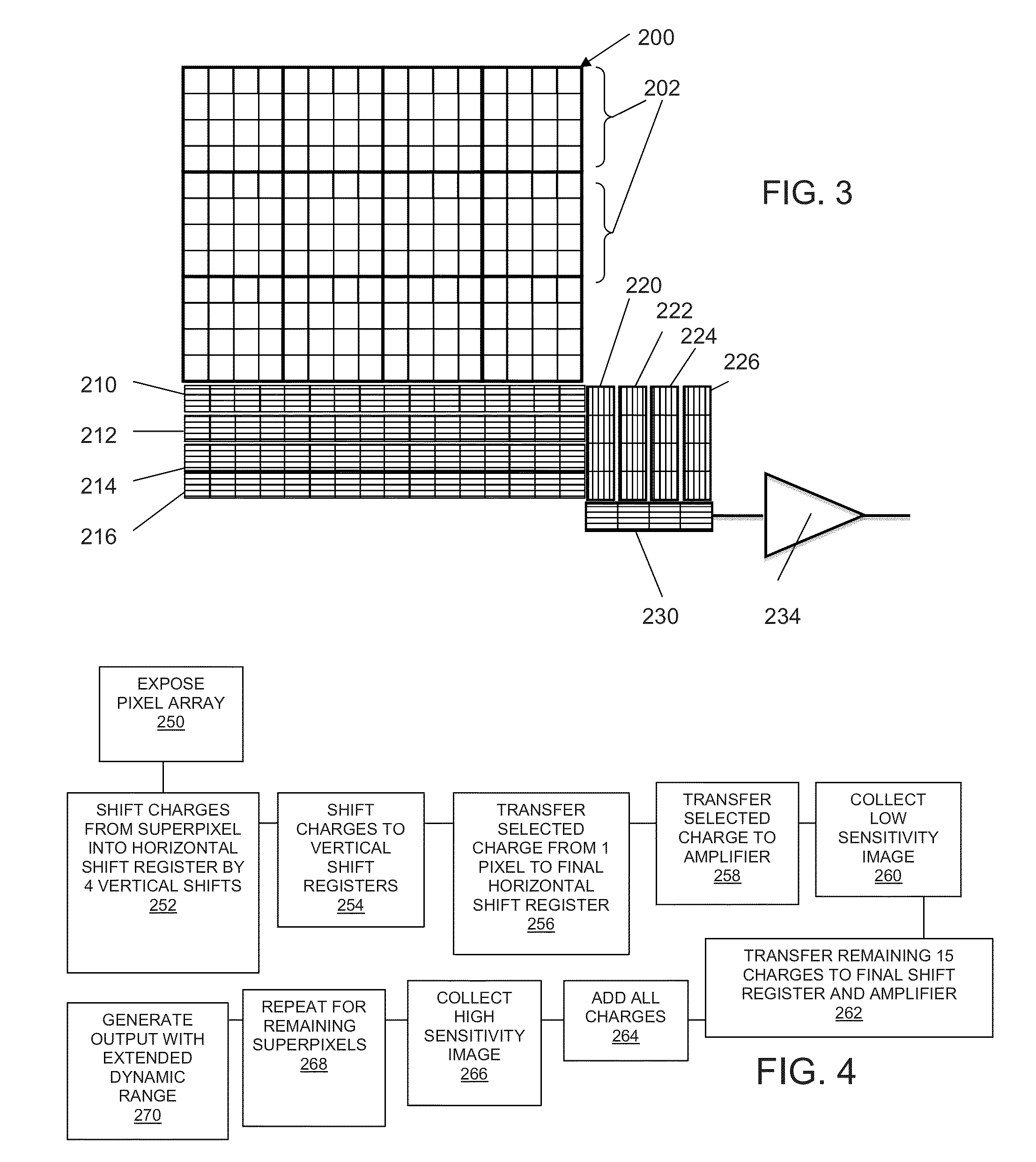
[0027]According to the present invention, photo-electrons generated by a CCD sensor are swept into shift registers in which charge summing can be performed. The variously on-chip binned exposures are then used to create a high dynamic-range image. An additional unique aspect is a custom output charge transfer register that allows read out of a binned image simultaneously with a sub-sampled, unbinned image.

[0028]A wide range of architectures may be used to perform on-chip binning to achieve simultaneous, high dynamic-range images, combined with greatly enhanced low-light sensitivity. Separate images, with different binnings can be used, or a CCD architecture can be used to simultaneously read out differently binned images. The exemplary embodiments described herein are not intended to be restrictive to any particular implementation. One skilled in the art will immediately recognize that the architectures incorporated in the examples described below may also be used for color CCDs by ...


PUM


Abstract

An image sensor comprises a pixel array having a plurality of pixel regions, wherein the pixel array is adapted to generate at least one signal from each pixel region and a separate signal from a subset of pixels within each pixel region, both during a single exposure period. In one embodiment, the sensor is in communication with a shift register which accumulates the separate signal and transfers the separate signal to an amplifier. The shift register further accumulates the at least one signal from the pixel region after the separate signal has been transferred to the amplifier and transfers the at least one signal to the amplifier.

Description

RELATED APPLICATIONS[0001]The present application claims the priority of U.S. Provisional Application No. 61 / 720,734, filed Oct. 31, 2012, the disclosure of Which is incorporated herein by reference in its entirety.FIELD OF THE INVENTION[0002]The invention relates to methods of extending the dynamic range of a sensor as sensor noise begins to limit the low-light end of the sensor's dynamic range. More specifically, the present invention relates to the use of spatially adaptive binning to enhance target detectability under low-light conditions.BACKGROUND OF THE INVENTION[0003]Despite major improvements in solid-state image sensor and digital camera technology, conventional digital cameras may have a maximum photo-signal storage capacity that limits the dynamic range of the particular system. The photo-signal charge is stored on a capacitor within the pixel area. The charge handling capacity is limited by the maximum voltage swing in the integrated circuitry and the storage capacitanc...

Claims


Application Information

Patent Timeline
IPC IPC(8): H04N5/243
CPCH04N5/35563H04N5/347H04N25/46H04N25/585H04N23/76
Inventor PUETTER, RICHARD C.JUNKKARINEN, VESA
Owner PIXON IMAGING
Why Eureka
Try Eureka