LED module

a technology of led modules and led modules, applied in the field of signs, can solve the problems of high manufacturing cost, insufficient epoxy filling, and insufficient epoxy filling in the led module,

Inactive Publication Date: 2014-05-01
KI NO CHUL
View PDF7 Cites 13 Cited by
  • Summary
  • Abstract
  • Description
  • Claims
  • Application Information

AI Technical Summary

Benefits of technology

[0011]The invention further provides an LED module that can be manufactured at a relatively low cost.
[0013]The invention further provides an LED module that can be manufactured in a relatively short time.

Problems solved by technology

However, conventional LED modules are disadvantageous in that, since they employ expensive epoxies to fix the components, the manufacturing costs are high.
Although LED modules are filled with expensive epoxies, the filled amount of epoxy cannot be detected.
Therefore, epoxy may be exceedingly or insufficiently filled in the LED module or the filled epoxy may be cured at one side in the LED module.
These deteriorate the quality of LED modules, e.g., waterproof performance, product reliability, etc.
If the LED module is filled with epoxy to the extent of the surface of the LED plate, cracks are created on the cured epoxy during usage.
Since foreign substances, such as water, dust, etc., easily invade the cracks, the LED plate may be damaged.
Since LEDs on the LED plate are coated with epoxy when it fills the LED module, this reduces the uniformity of the distribution of diffused light in the LED module.
In addition, since epoxy filling the LED module requires approximately 24 hours to be cured, it takes a long time to manufacture an LED module.

Method used


Image

  • LED module
  • LED module
  • LED module

Examples


Embodiment Construction

[0020]Hereinafter, exemplary embodiments of the invention are described in detail with reference to the accompanying drawings. Although the drawings represent an embodiment of the invention, the drawings are not necessarily to scale and certain features may be exaggerated or omitted in order to better illustrate and explain the invention.

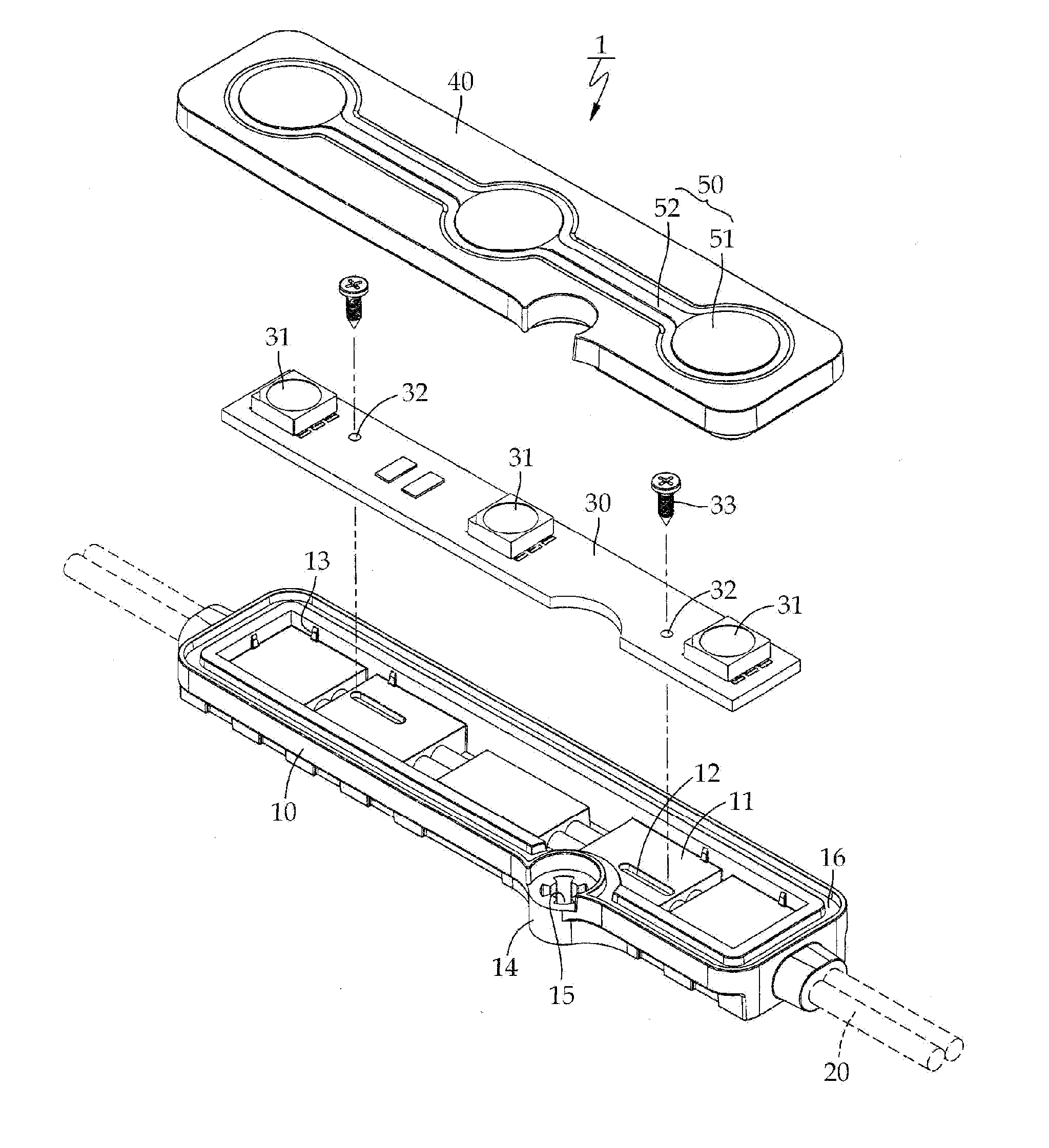
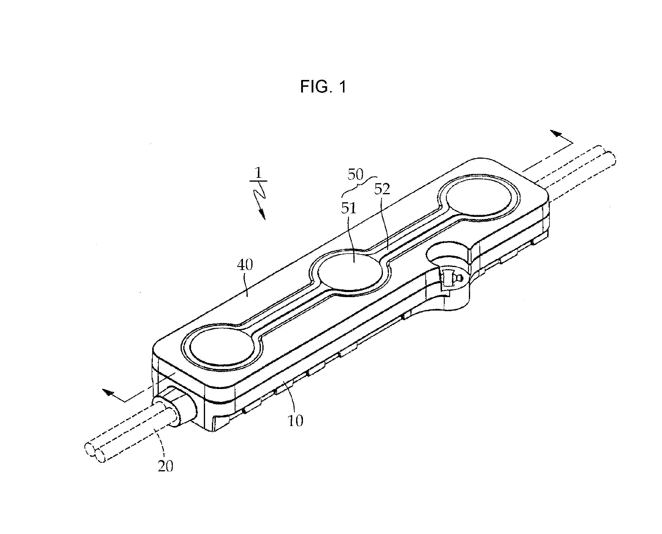
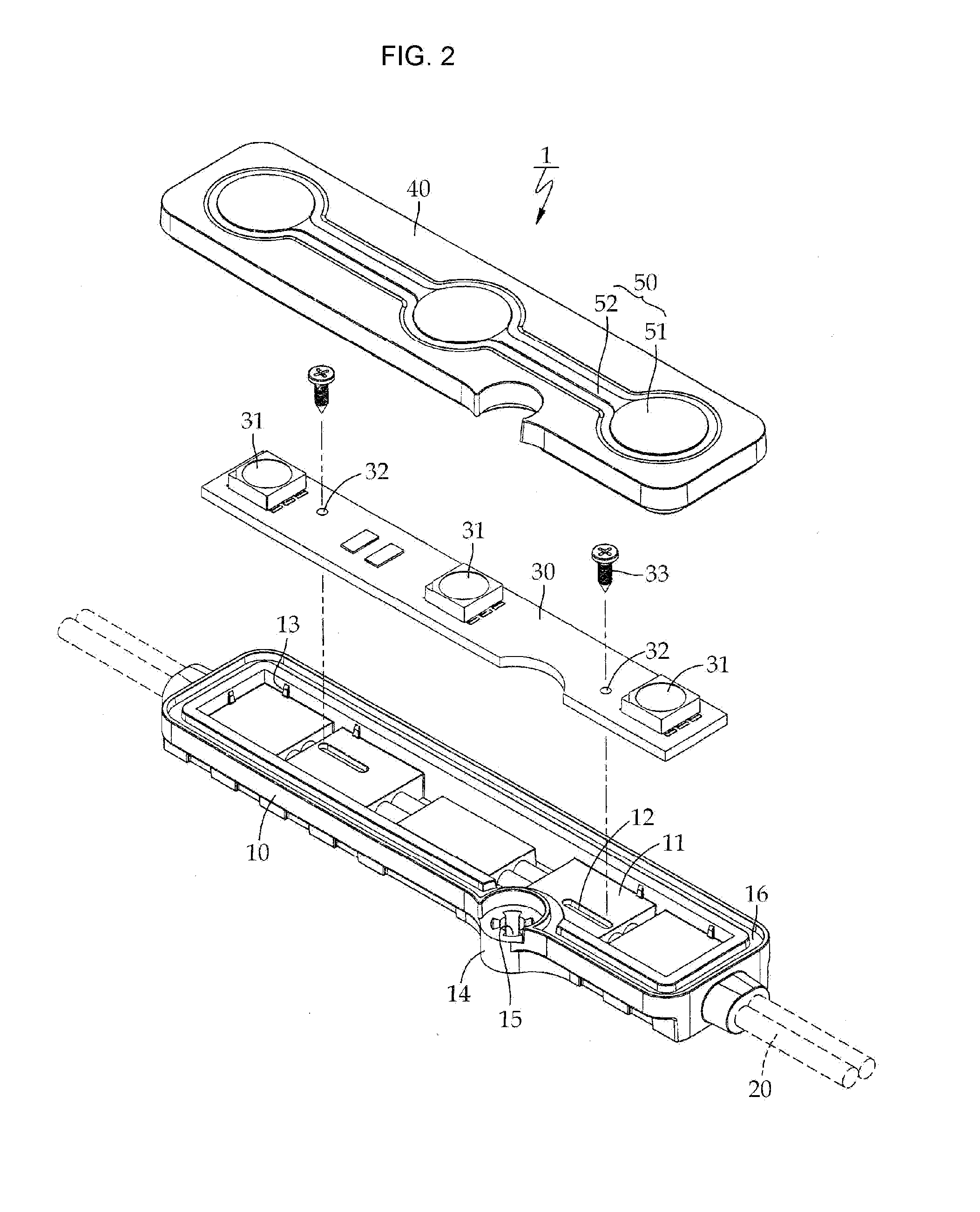
[0021]As shown in FIGS. 1 to 3, the LED module 1 comprises a base plate 10, a plate 30, a cover 40 and a lens part 50.

[0022]As shown in FIGS. 1 and 2, the base plate 10 is integrally coupled with wires 20 via an injection molding. That is, the wires 20 are injected inside the base plate 10, so that they are integrally formed as a body.

[0023]The base plate 10 is shaped as a box where the top side is opened, forming a reception space.

[0024]The base plate 10 forms a number of placements 11, shaped as blocks, on the bottom. The placements 11 are located spaced apart from each other at a certain distance. The wires 20 are located between the placements 1...


PUM


Abstract

A light emitting diode (LED) module is provided that emits uniform light in terms of the distribution of diffused light. The LED module comprises: a base plate integrally formed with electrical wires via an injection molding, wherein the base plate forms a reception space; a plate on which a number of LEDs are installed, wherein the plate is placed in the reception space of the base plate; bolts coupling the plate to the base plate; a cover that is fixed to the base plate via ultrasonic welding; and a lens part that is formed in the cover via a double injection molding, wherein the lens part comprises fluorescent materials and has various colors.

Description

BACKGROUND OF THE INVENTION[0001]1. Field of the Invention[0002]This invention relates to signs, and more particularly, to a light emitting diode (LED) module with florescent lenses that can emit uniform light in terms of the distribution of diffused light.[0003]2. Description of the Related Art[0004]Light Emitting Diode (LED) modules are in general installed to signs for advertisements or walls that require illumination. An LED module includes a base plate, shaped as a box where the top side is opened; an LED plate, fixed in the base plate, including a number of LEDs; and an electric wire for supplying electric power to the LED plate.[0005]The LED module is configured so that the LED plate is exposed to the outside. When an epoxy is applied to the base plate where electric wires are buried so that it can be filled such an extent to cover the surface of the exposed LED plate, the exposed LED plate can be protected. LED modules are fixed to signs for advertisements or walls that requ...

Claims


Application Information

Patent Timeline
Patent Type & Authority Applications(United States)
IPC IPC(8): F21V9/16
CPCF21V9/16F21V19/0055F21V21/002F21S4/10F21Y2115/10F21V5/10G09F9/33
Inventor KI, NO CHUL
Owner KI NO CHUL
Why Eureka
Try Eureka