Fire evacuation installation

a fire and installation technology, applied in the field of emergency evacuation installation, can solve the problems of affecting affecting the safety of the building, and spreading of fire, so as to relieve the concerns of possible accidents, prevent damage and corrosion, and contribute to the aesthetics of the building

Active Publication Date: 2014-05-08
E&F TECH CO LTD
View PDF23 Cites 11 Cited by
  • Summary
  • Abstract
  • Description
  • Claims
  • Application Information

AI Technical Summary

Benefits of technology

[0011]According to the present disclosure as described above, various components of the present emergency evacuation installation attached to the balcony are not exposed to the outside as the installation is neatly enclosed to blend in the exterior of a building while in constant readiness for deployment in case of emergency and thereby allows unhindered use thereof with a contribution to aesthetics of the building. Further, the emergency evacuation installation is configured to prevent damages and corrosions caused by rain and such elements by cutting off rainwater in particular, so as to relieve the concerns of possible accident due to damage of the parts.
[0012]In addition, the present emergency evacuation installation at the balcony of a building provides the occupants with a protected rescue pod to enter for evading flames and

Problems solved by technology

Besides, the emergency exit, for example is where the most people converge and is thus occasionally incapacitated.
In this case, the emergency exit tends to function as the smoke chimney, rather resulting in the spread of a fire.
There have been reports of a substantial number of casualties occurred due to the adverse effect of the fire door which exposes the victims unprotected to the flame and even more deadly poisonous gas.
However, such fac

Method used


Image

  • Fire evacuation installation
  • Fire evacuation installation
  • Fire evacuation installation

Examples


first embodiment

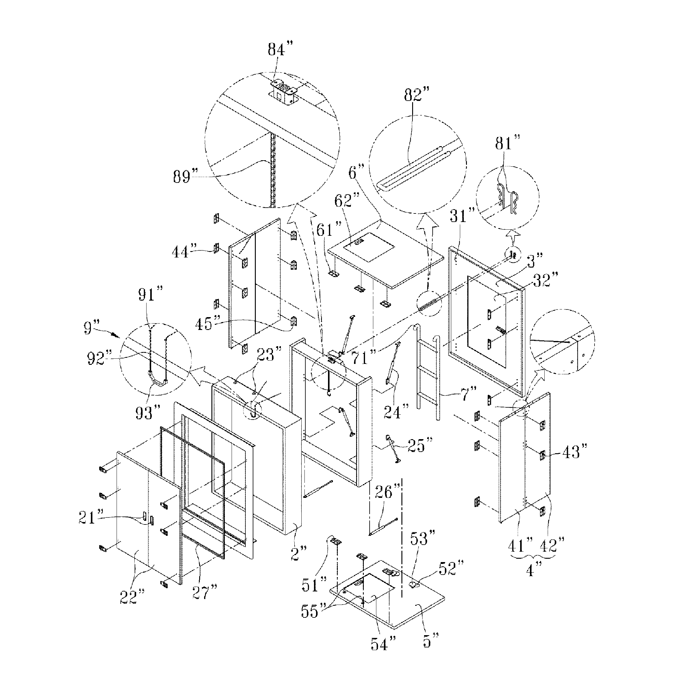
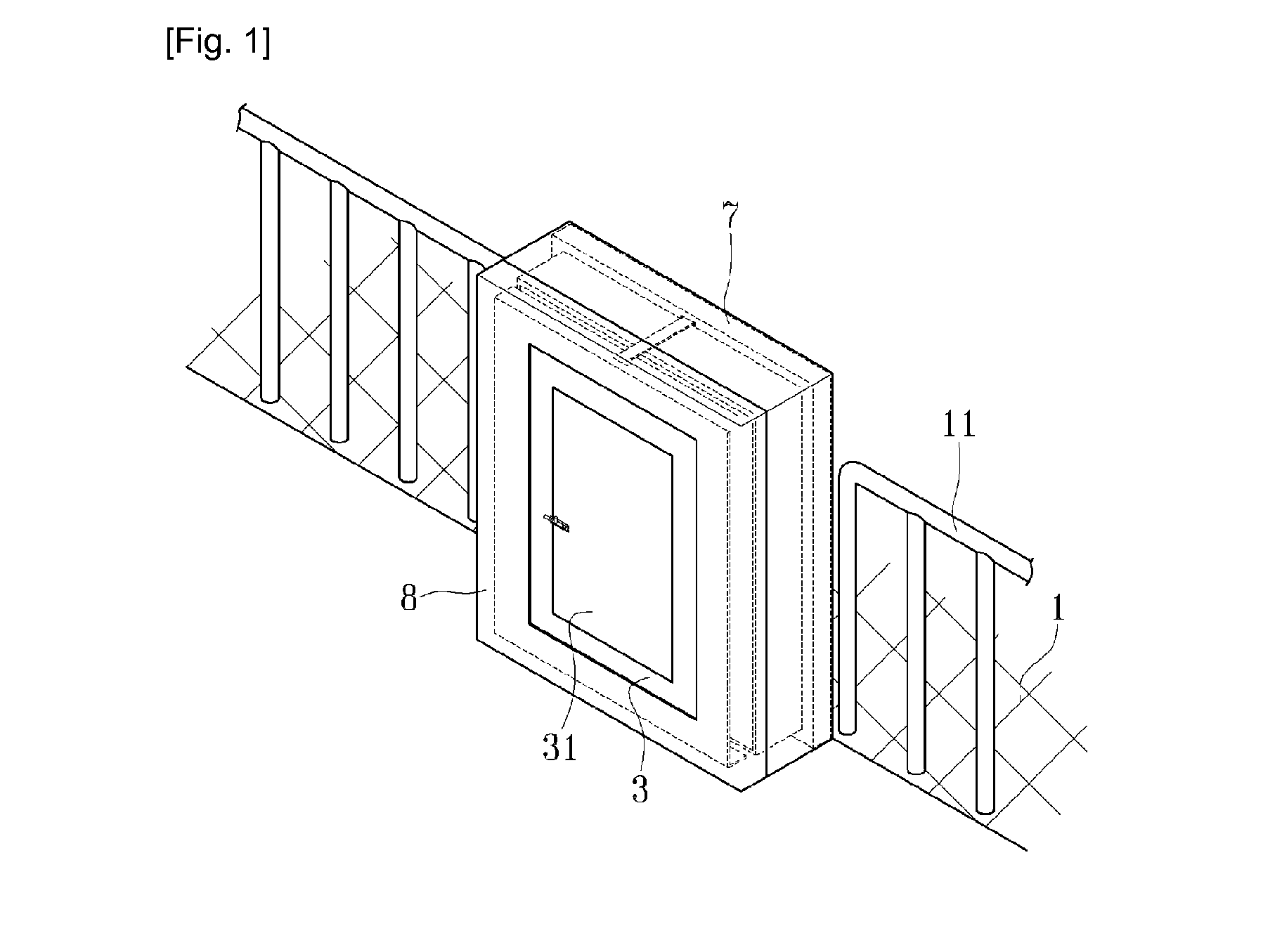
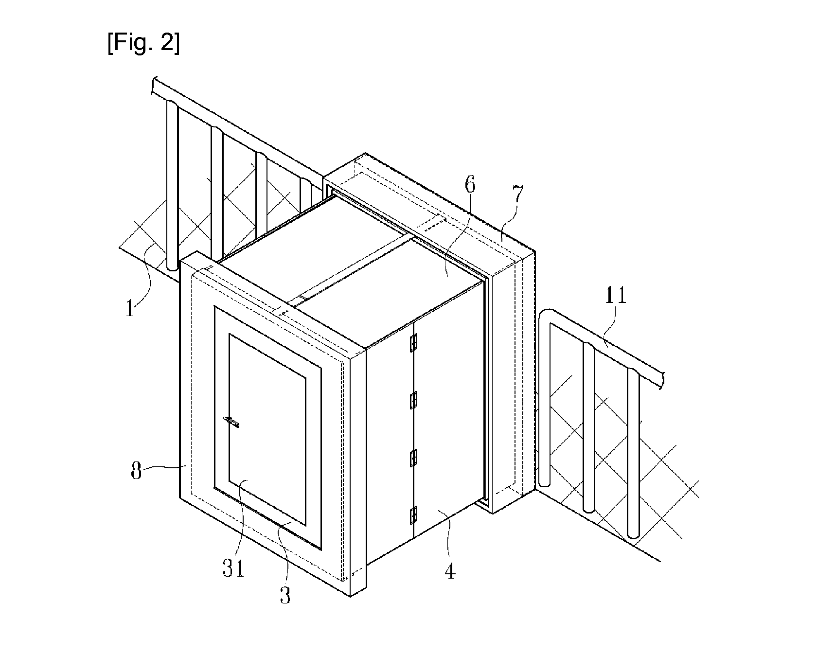
[0022]As illustrated in the drawings, the emergency evacuation installation may be in a rectangular form and fixed to a veranda 1 of a building at a railing 11. The present installation includes a rectangular frame 2 having an entrance 21 (doors 22′ FIG. 18 and 22″FIG. 26a) at the front side, a rear panel 3 disposed rearward of the frame 2 and having an exit door 31, two side panels 4, a bottom panel 5 and a top panel 6, which jointly constitute a box-type of emergency escape shelter and is collapsible as bellows.

[0023]The present installation also includes a front cover 7 and a rear cover 8. The front cover 7 conforms to and tightly surrounds the rectangular frame 2 and extends rearward until it terminates at a first press-fit flange 71 which is bent inwardly at right angle. The rear cover 8 includes a main body fixed to the rear surface of the rear panel 3 with an opening formed not to interfere with the opening and closing of the exit door 31 and outer edges extending forward fr...

second embodiment

[0025]FIG. 9 is a plan view of a collapsed state of an emergency evacuation installation according to the present disclosure, FIG. 10 a plan view of an expanded state thereof, and FIGS. 11A and 11B are side cross-sectional views of the same, wherein one of the first and second press-fit flanges 71, 82 extends further inward and bends right toward the other along a slight extension and then bends again perpendicularly and outwardly to additionally form a draining section 83.

[0026]It is important to address corrosion which occurs rapidly around the components of the emergency evacuation installation including vulnerable hinges to the direct exposure to rainwater or humid winds causing reduced durability thereof. In view of this, the enclosure of the present embodiment is advantageously provided with a protective means as the draining section 83 arranged for collecting and expelling any intruded water.

third embodiment

[0027]FIG. 12 is a plan view of a collapsed state of an emergency evacuation installation according to the present disclosure, FIG. 13 a plan view of an expanded state thereof, and FIGS. 14A and 14B are side cross-sectional views of the same, wherein the emergency evacuation installation has sealing mounting ribs 73, coupling ribs 84 and a sealing member 9. In this example, the sealing mounting ribs 73 are adjacent to the rear ends of the front cover 7 and extend by branching inwardly followed by rearward extensions to jointly form grooves along the rear boundary line of the front cover 7. The coupling ribs 84 extend at right angle from the front ends of the rear cover 8 and bend again to the front so that they are distally inserted in the grooves of the sealing mounting ribs 73. At this time, the sealing member 9 may have the shape of a rectangular ring with a corresponding groove along the rear ends of the front cover 7.

[0028]As described above, the seal member may be more positiv...


PUM


Abstract

Disclosed is a fire evacuation installation. When evacuees are not able to evacuate through an emergency exit or other means of evacuation when a fire occurs, the fire evacuation installation may safely protect the evacuees from flames and poisonous gas until rescue workers arrive. Further, the fire evacuation installation may be prevented from being damaged by exposure to rain, and the fire evacuation installation may have an elegant outer appearance and be more easily installed. In addition, the fire evacuation installation may be selectively moved between the floors of a building.

Description

CROSS-REFERENCE TO RELATED APPLICATION[0001]This application claims the benefit of Korean Patent Application No. 10-2011-0060457, filed on Jun. 22, 2011 in the Korean Intellectual Property Office, the disclosure of which is incorporated herein by reference.TECHNICAL FIELD[0002]The present disclosure in one or more embodiments relates to an emergency evacuation installation against fire. More particularly, the present disclosure relates to an emergency evacuation installation for providing evacuees with a backup shelter when isolated from a vulnerable emergency exit or other means of evacuation until the arrival of rescue workers against firing or burning poisonous gas, while the evacuation installation is normally self-concealed resisting damages from rain and weather elements, swiftly attached, possessing an elegant external appearance, and is selectively movable between the floors of a building.BACKGROUND[0003]As the majority of the population is concentrated in cities, ever incre...

Claims


Application Information

Patent Timeline
IPC IPC(8): A62B3/00E04H9/00
CPCE04H9/00A62B3/00E04H1/1261
Inventor NAM, JUNG-OMIN, SE-HONG
Owner E&F TECH CO LTD
Why Eureka
Try Eureka