
Fiber Bragg Grating Pressure Sensor with Adjustable Sensitivity

a fiber bragg grating and pressure sensor technology, applied in the direction of fluid pressure measurement by electric/magnetic elements, measuring devices, instruments, etc., can solve problems such as damage or change the characteristics of fibers

Pending Publication Date: 2014-05-08
ABTAHI MOHAMMAD +2
View PDF9 Cites 29 Cited by
  • Summary
  • Abstract
  • Description
  • Claims
  • Application Information

AI Technical Summary

Benefits of technology

The present invention describes a new technique for a pressure sensor based on fiber grating. The invention allows for adjusting sensitivity over a wide range and can provide a calibration screw to do so. Additionally, the invention avoids direct contact between the grating and the material in which pressure is measured, which could damage the grating over time. The same pressure sensor can be used for various applications as the sensitivity and pressure range can be adjusted for each application.

Problems solved by technology

Note that some materials could damage or change the characteristics of the fiber over the time.

Method used


Image

  • Fiber Bragg Grating Pressure Sensor with Adjustable Sensitivity
  • Fiber Bragg Grating Pressure Sensor with Adjustable Sensitivity
  • Fiber Bragg Grating Pressure Sensor with Adjustable Sensitivity

Examples


Embodiment Construction

[0024]With reference to the annexed drawings the preferred embodiment of the present invention will be herein described for indicative purpose and by no means as of limitation.

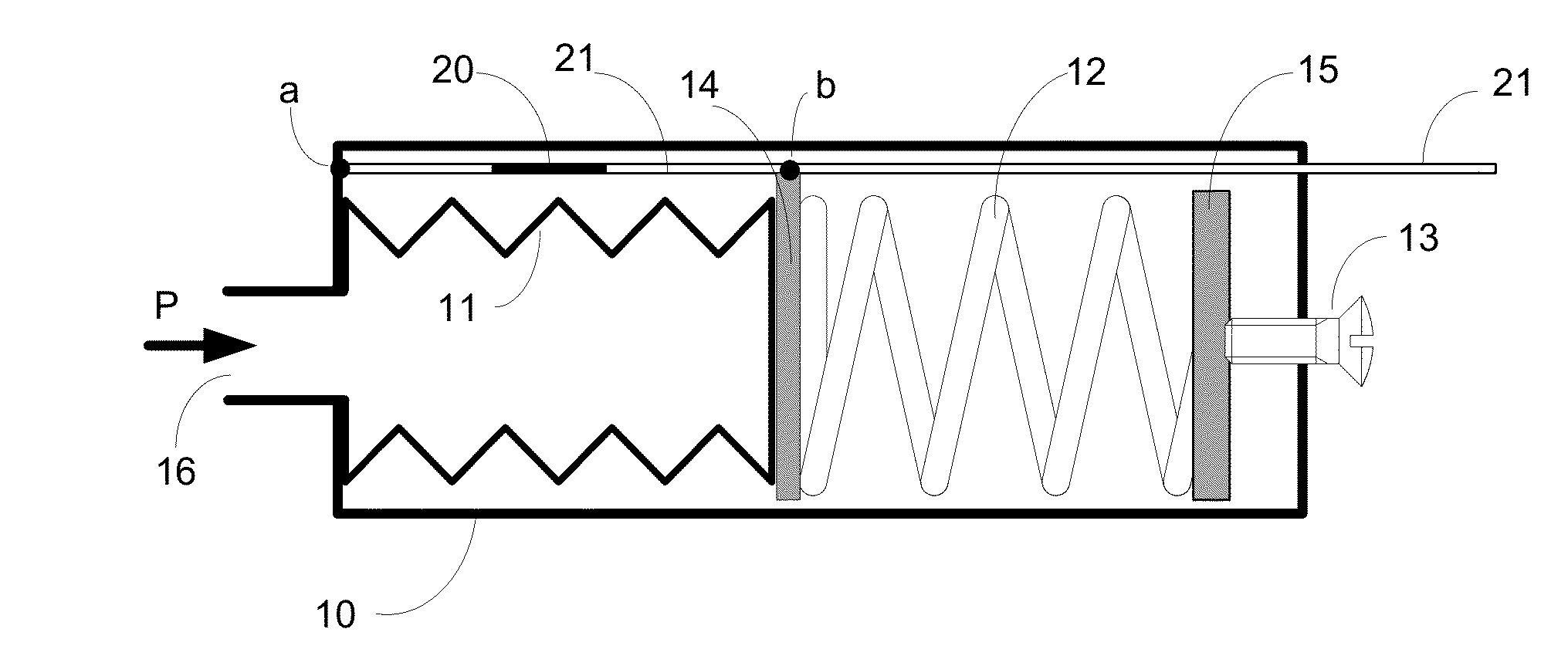
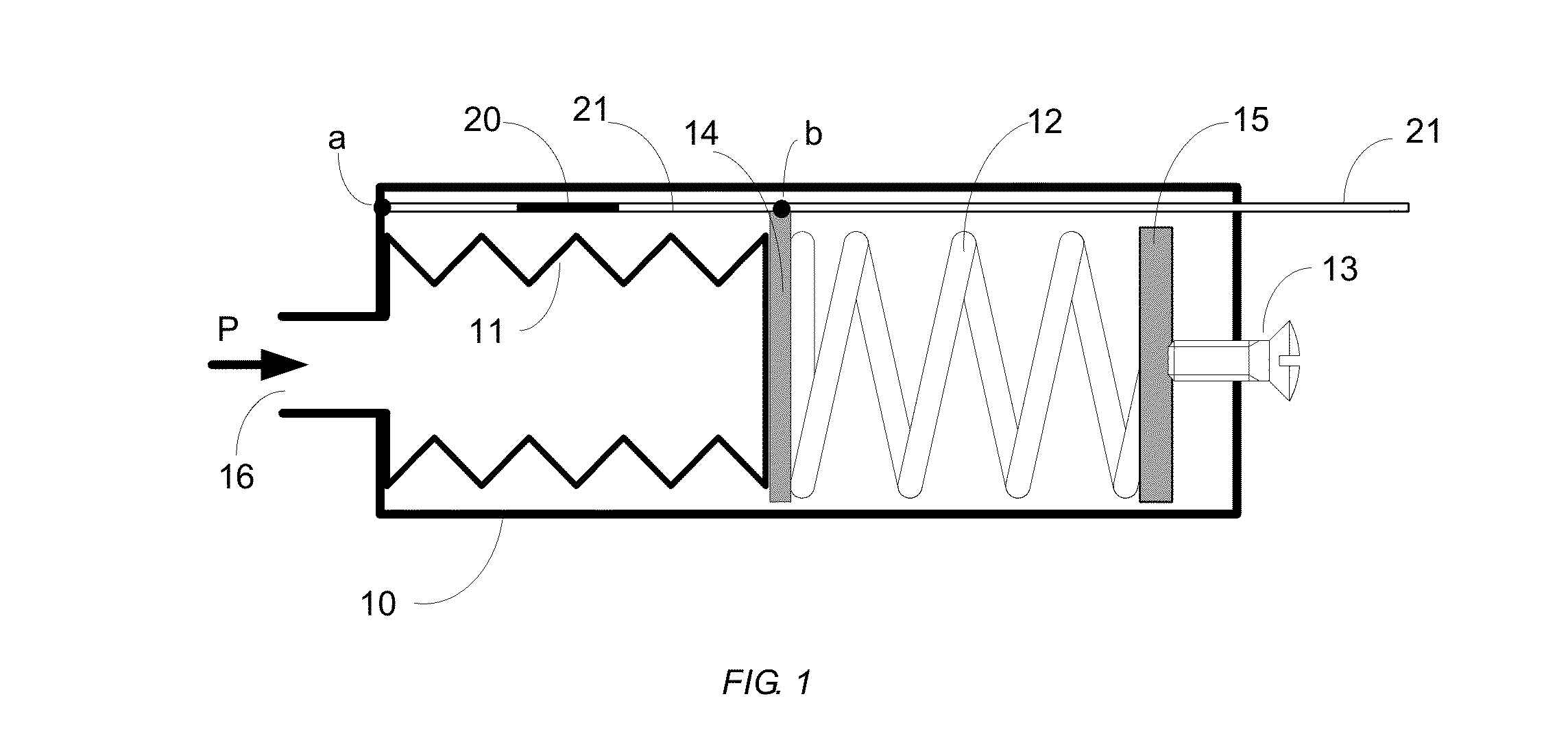
[0025]Referring to FIG. 1, there is shown the principles of the present invention in a schematic diagram where a metal bellows 11, a spring 12 and a screw 13 are connected and fixed to each other using the connectors 14 and 15. All components are tightly placed in a cylindrical metal tube 10. The tube 10 is completely sealed except for a hole 16 to let the gas (or liquid) with a pressure of P enter the bellows.

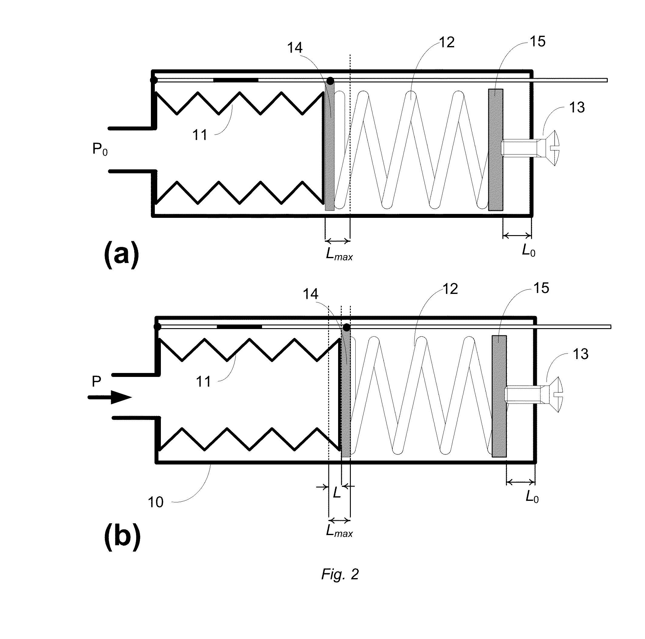
[0026]A fiber Bragg grating 20 written in a piece of optical fiber 21 is fixed to the tube at one end in point “a” and to the connector 14 in point “b”. The fiber 21 goes then out of tube 10 and will be connected to the sensor interrogation system for pressure monitoring. When the pressure inside the below is higher than the air pressure, the bellow expands and as a result the FBG will be stretched and a...


PUM


Abstract

A new type of optical pressure sensor with adjustable sensitivity is proposed based on the fiber Bragg grating (FBG). In this technique, the pressure changes the length of a metal bellows which is placed behind a spring. The fiber grating is fixed over the bellows between a fixed position and the connection point of bellows and spring. The wavelength change of FBG is caused by the change in the bellows length; however, the spring controls the total length expansion of the bellows. It will bring two benefits: first it is easy to change the pressure sensing range by changing the spring rate; and secondly the spring improves the linearity of the wavelength sift due to the pressure. The FBG is installed outside of the bellows and is not in contact with the material in which the pressure should be measured (gas or liquid) in contrast with other pressure sensors where the FBG is inside the bellows. This is an important issue because some materials could damage or change the characteristics of the fiber over the time.The pressure range and the sensitivity of the proposed pressure sensor can be adjusted over a wide range simply and only by tuning two calibration screws, while all components of sensor remain the same.

Description

BACKGROUND OF INVENTION[0001]The pressure sensors are used in various pressure ranges and sensitivities in different applications including medical, military and civil applications as well as in the oil and gas industries. The three major technologies for pressure measurement with optical fiber sensors (OFS) are intensity-based, Fabry-Pérot and fiber Bragg gratings (FBG). Each of them has some advantages and drawbacks which make them the best choice for some applications.[0002]In the first technique, the coupled light intensity into an optical fiber is changed when the pressure moves a membrane. The membrane movement, however, in the Fabry-Pérot sensors changes the cavity length. The interference pattern created by the cavity could be used to measure the diaphragm deflection and thus the pressure change.[0003]Since FBG intrinsic pressure sensitivity is not very high, the FBG-based OFS are normally designed to measure the pressure indirectly by measuring the strain instead which incr...

Claims


Application Information

Patent Timeline
IPC IPC(8): G01L11/02
CPCG01L11/025G01L1/246G01L7/065
Inventor ABTAHI, MOHAMMADLONG, PINNAYDENOV, NIKOLAY
Owner ABTAHI MOHAMMAD
Learn More