Evaporative emission control

Active Publication Date: 2014-05-08
FORD GLOBAL TECH LLC
View PDF4 Cites 17 Cited by
  • Summary
  • Abstract
  • Description
  • Claims
  • Application Information

AI Technical Summary

Benefits of technology

The patent text describes a method for reducing emissions in vehicles that use evaporative emission control systems. The method involves redirecting air from the engine's air cleaner to the fuel vapor canister, which stores fuel vapors. This allows the canister to be purged even when there is low vacuum induction in the engine. By purging multiple regions of the canister simultaneously, a time required to complete purge is lowered, attaining zero bleed emissions from the canister. Additionally, the method maintains a combustion air-to-fuel ratio, improving exhaust emissions and emissions compliance.

Problems solved by technology

However, the inventors herein have recognized issues with the above approach.
For example, in engine applications that operate with low vacuum air induction, or near atmospheric pressure (as measured post throttle body in the engine's intake manifold), the small amount of vacuum may not be enough to sufficiently purge the fuel vapor canister.
As such, if the canister is not completely purged, exhaust hydrocarbons may slip into the atmosphere, degrading exhaust emissions and making the vehicle emissions non-compliant.
In addition, the low vacuum may increase the engine operation time required to purge the fuel vapor canister.
The unintended increase in engine run time for the hybrid vehicle can degrade vehicle fuel economy.

Method used


Image

  • Evaporative emission control
  • Evaporative emission control
  • Evaporative emission control

Examples


embodiment 400

[0046]Now turning to FIG. 4, an alternate embodiment 400 is shown for a fuel vapor canister. In the depicted embodiment, the external housing of the canister on the second side 328 is modified to reduce the number of connections. In particular, each of second air vent 314 and third air vent 318 is configured to receive air via a common intake vent 402. Further, within the canister, second air vent 314 and third air vent 318 are separated from each other by vent dividing wall 434. In addition, the canister may include an air gap 404 for lowering restriction within the canister during purge. The substantially lower restriction allows engine air induction to be mimicked, improving canister purging efficiency during low vacuum availability. In some embodiments, the different chambers or regions of the canister may be divided with an air gap relevant to the purge port to further reduce purge flow restrictions.

embodiment 500

[0047]FIG. 5 shows a further embodiment 500 for the fuel vapor canister. In the depicted embodiment, the external housing of the canister on side 332 is adjusted to reduce the number of connections. In particular, a purge tube 502 having an external passageway (or external routing) is coupled between the purge ports to reduce the number of connections for purging by one. As such, this eliminates the direct connection between first purge port 306 and purge line 142 via first purge branch 342 (See FIG. 3). Instead, fuel vapors released along first purge port 306 may be directed along purge tube 502 towards second purge port 304, from where there may be directed to purge line 142 together. In this way, by using an external passageway, the number of connections coupling the canister to the purge line are reduced, making purge control easier while also reducing losses incurred due to leakage. By using a purge port that runs perpendicular to the air vents, canister restriction during purg...


PUM


Abstract

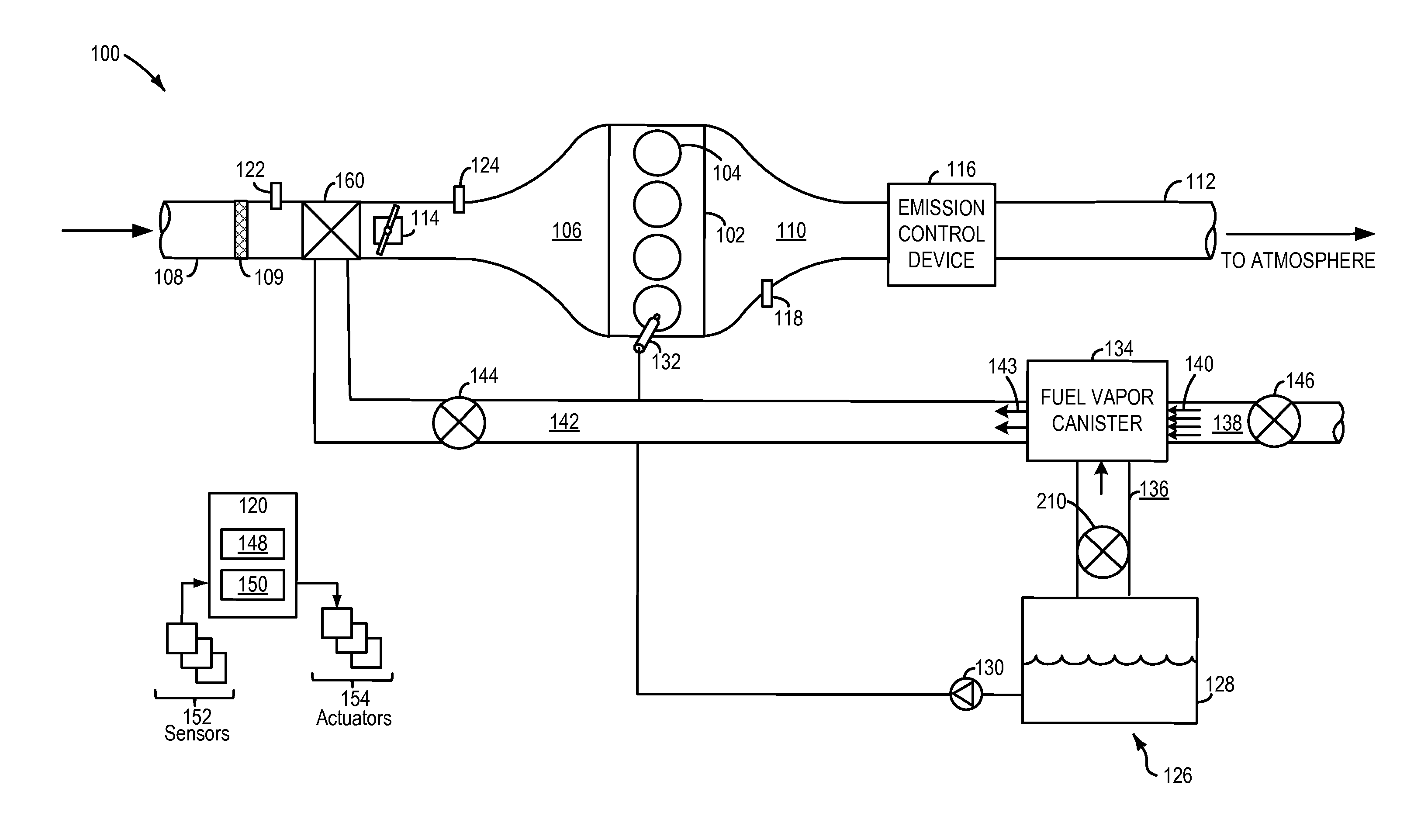
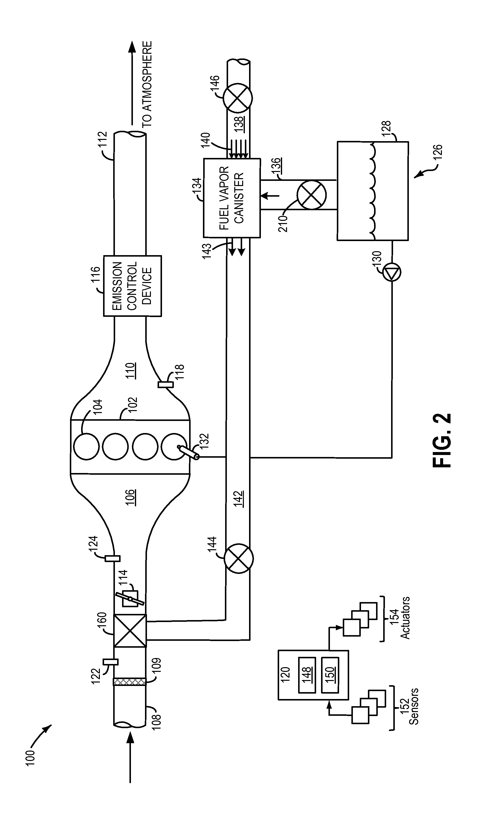
Methods and systems are provided for purging a multi-port canister into an engine intake. Air is circulated through the canister and a resulting purge air is directed to an intake passage upstream of a throttle in engine configured with a throttle body. An amount of fresh intake air received at the intake passage is corresponding decreased.

Description

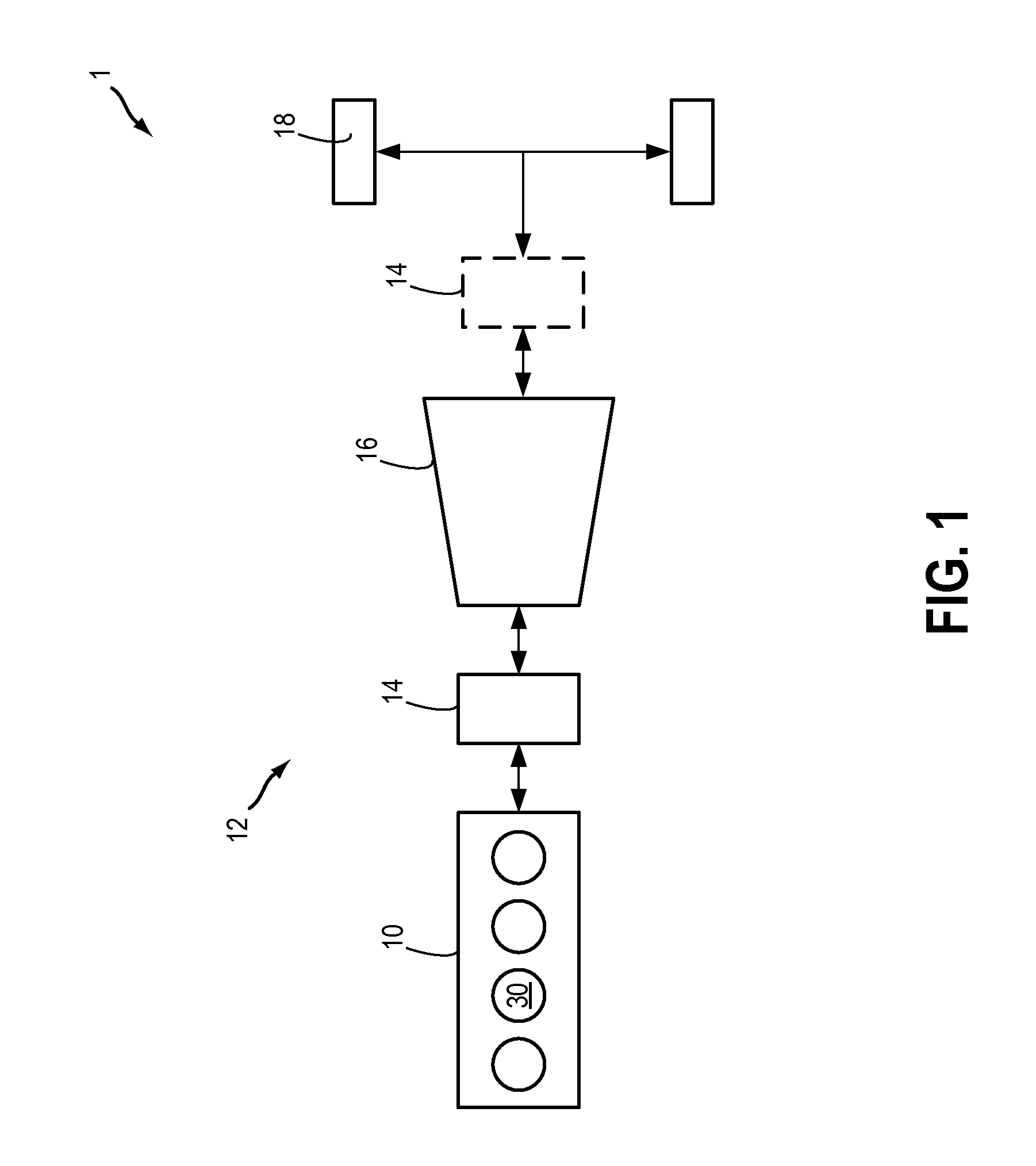
FIELD[0001]The present invention relates to purging of a canister coupled to a fuel system in hybrid vehicles and other vehicles with limited engine operation times.BACKGROUND AND SUMMARY[0002]Vehicles may be fitted with evaporative emission control systems to reduce the release of fuel vapors to the atmosphere. For example, vaporized hydrocarbons (HCs) from a fuel tank may be stored in a fuel vapor canister packed with an adsorbent which adsorbs and stores the fuel vapors. At a later time, when the engine is in operation, the evaporative emission control system allows the fuel vapors to be purged into the engine intake manifold from the fuel vapor canister. The fuel vapors are then consumed during combustion.[0003]In one example described by Covert et al. in U.S. Pat. No. 5,878,729, a fuel vapor canister includes a plurality of inlet ports and purge ports regulated by respective valves. During operation of the engine, the purge valves and the air inlet valves are opened to supply a...

Claims


Application Information

Patent Timeline
IPC IPC(8): F02M33/04
CPCF02M33/04F02M25/0836F02M25/0854F02M25/089F02D29/02F02D41/004F02M25/0809
Inventor KRAGH, NIELS CHRISTOPHERHEIM, MICHAEL G.
Owner FORD GLOBAL TECH LLC
Why Eureka
Try Eureka