Led-based emergency lighting equipment and methodology

a technology of emergency lighting and led-based batteries, which is applied in the direction of amplitude demodulation, lighting support devices, and with built-in power, can solve the problems of battery maintenance mode power consumption levels that are too high, and the need for relatively large and heavy batteries and battery chargers, so as to prolong the useful life of batteries and lower the power consumption level of battery maintenance mod

Active Publication Date: 2014-05-08
HUBBELL LIGHTING INC
View PDF4 Cites 19 Cited by
  • Summary
  • Abstract
  • Description
  • Claims
  • Application Information

AI Technical Summary

Benefits of technology

[0011]According to an exemplary implementation of an embodiment of the present invention, the system comprises a microprocessor executing a pulse charging algorithm to lower battery maintenance mode power consumption levels and extend the useful life of the battery.

Problems solved by technology

Because these incandescent light sources have relatively low efficacy levels, the batteries required to power them for the 90 minute run times mandated by NFPA 101 life safety codes were heavy and bulky VRLA types.
Thus, one of the problems for traditional emergency lighting units is the need for relatively large and heavy batteries and battery chargers.
While the advances in LED lighting technology have made the LED a viable replacement lighting source in general purpose lighting fixtures the costs associated with the LED light source are significantly higher than more established traditional light sources.
The disadvantageous high costs are likewise associated with conventional emergency lighting units attempting to use LED light sources.

Method used


Image

  • Led-based emergency lighting equipment and methodology
  • Led-based emergency lighting equipment and methodology
  • Led-based emergency lighting equipment and methodology

Examples


Embodiment Construction

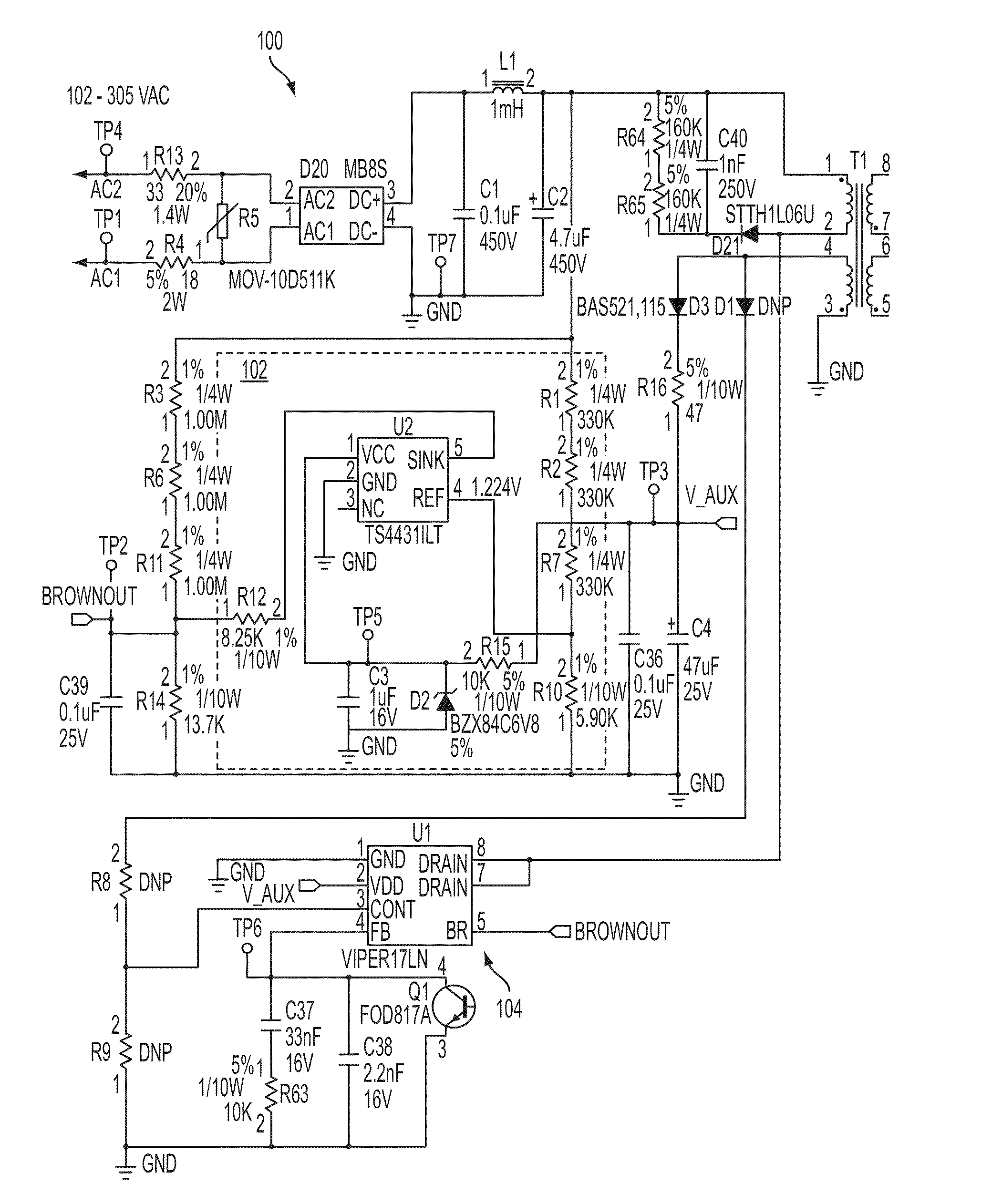
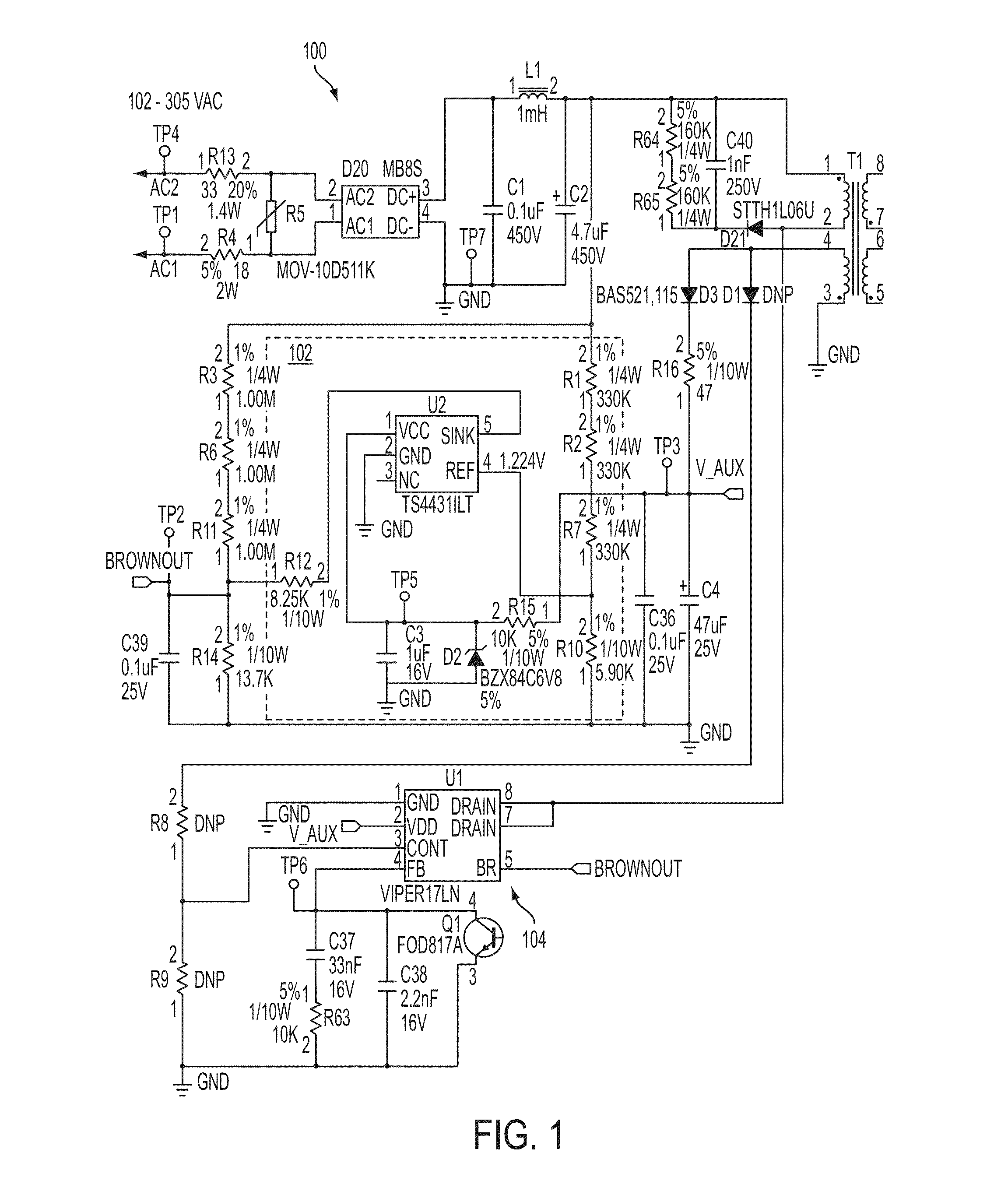
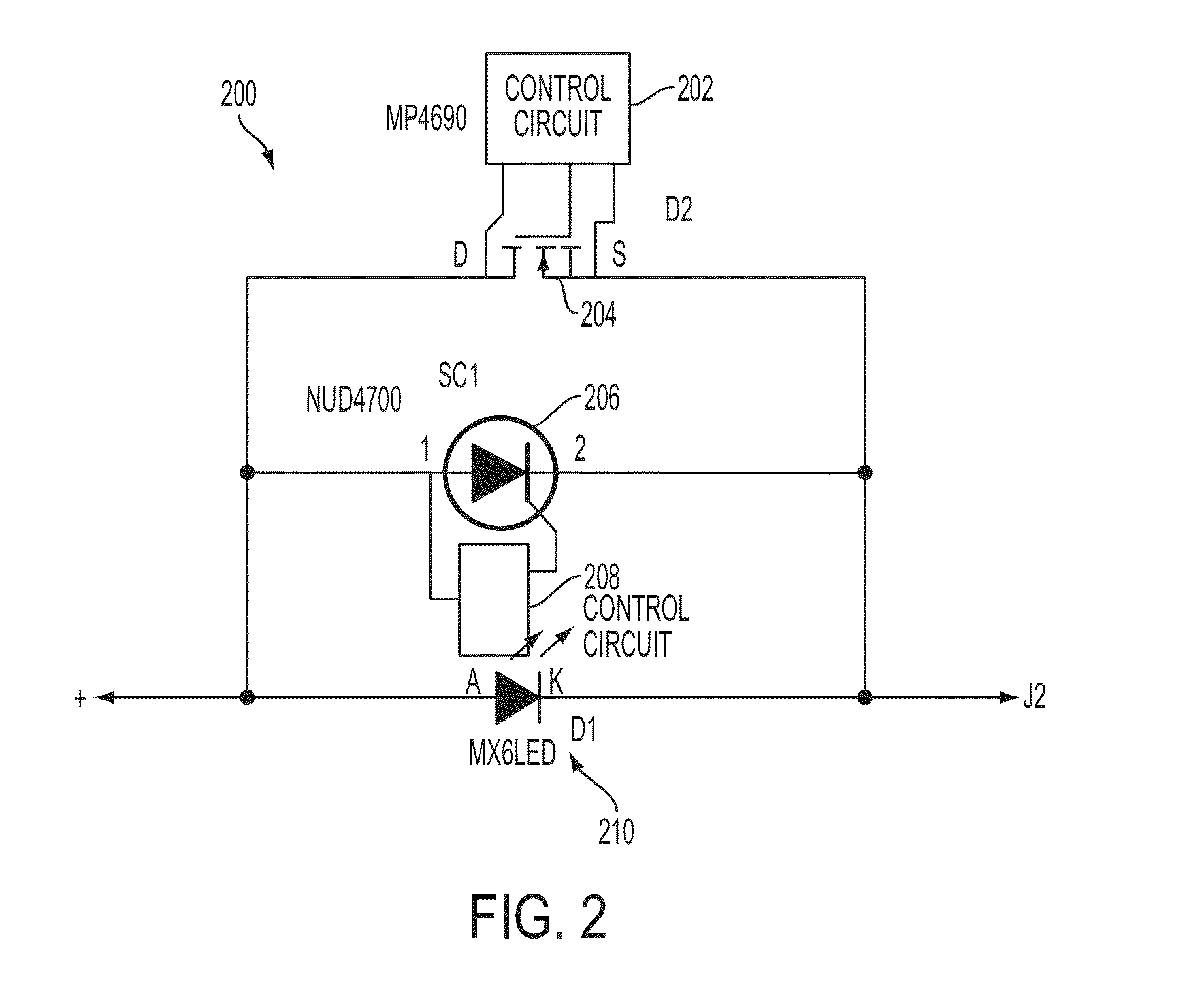
[0031]Referring now to the drawings, wherein like reference numerals designate identical or corresponding parts throughout the several views, embodiments of the present invention are shown in schematic detail.

[0032]The matters defined in the description such as a detailed construction and elements are nothing but the ones provided to assist in a comprehensive understanding of the invention. Accordingly, those of ordinary skill in the art will recognize that various changes and modifications of the embodiments described herein can be made without departing from the scope and spirit of the invention. Also, well-known functions or constructions are omitted for clarity and conciseness. Certain exemplary embodiments of the present invention are described below in the context of commercial application. Such exemplary implementations are not intended to limit the scope of the present invention, which is defined in the appended claims.

[0033]Certain terms of art that may be used in the descr...


PUM


Abstract

Systems and methods provide LED-based emergency lighting utilizing AC-DC switch mode power conversion technology, NiMH battery technology, and emergency lighting lamps that use high power white LEDs as the emergency lighting source. A low voltage microprocessor based circuit design reduces the battery input voltage for the unit to a nominal level of 2.4VDC. The microprocessor executes a pulse charging algorithm to lower battery maintenance mode power consumption levels and extend the useful life of the battery. Brownout detection technology does not require the determination of the AC input voltage level or transmission of the brownout detection signal to the secondary side of the circuit. A rechargeable battery is charged by a charge current selectively set to a bulk charge value, a trickle charge high value, or a trickle charge low value based on sampling of the voltage of the rechargeable battery and the charge current.

Description

CROSS-REFERENCE TO RELATED APPLICATION[0001]This application relates to U.S. Pat. No. 8,258,705 issued Sep. 4, 2012, and pending U.S. patent application Ser. No. 13 / 220,002 filed Aug. 29, 2011, the disclosures of which (including all attachments filed therewith) are hereby incorporated by reference in their entirety.BACKGROUND OF THE INVENTION[0002]1. Field of the Invention[0003]The invention is in the field of LED-based emergency lighting. Generally, LED-based emergency lighting systems, equipment and methodologies according to exemplary embodiments of the present invention utilize AC-DC switch mode power conversion technology, NiMH battery technology, and emergency lighting lamps that use high power white LEDs as the emergency lighting source.[0004]2. Discussion of the Background of the Invention[0005]For many years commercial two lamp emergency lighting unit designs have primarily been based around three key design elements to achieve costs that were acceptable in the marketplace...

Claims


Application Information

Patent Timeline
Patent Type & Authority Applications(United States)
IPC IPC(8): H02J9/06H03K5/24H02J7/00
CPCH02J9/061H03K5/24H02J7/007F21V21/30F21V29/507F21V29/74F21Y2115/10F21S9/022H02J7/0071H02J7/02H02J2207/20H05B45/56H02J7/04H02J7/00714H02J7/0013H02J7/00712
Inventor HAN, LEILANE, JOHN EVAN
Owner HUBBELL LIGHTING INC
Why Eureka
Try Eureka