Dc-dc driver device having input and output filters, for driving a load, in particular an LED unit

a driver device and driver technology, applied in the direction of electric variable regulation, process and machine control, instruments, etc., can solve the problems of high deformation of converter performance, size, reliability and lifetime, and achieve the effects of low cost, low cost and high power factor

Active Publication Date: 2014-05-08
KONINKLIJKE PHILIPS ELECTRONICS NV
View PDF11 Cites 27 Cited by
  • Summary
  • Abstract
  • Description
  • Claims
  • Application Information

AI Technical Summary

Benefits of technology

[0010]It is an object of the present invention to provide a driver device for driving a load, in particular an LED unit comprising one or more LEDs, particularly providing a high power factor, a virtually constant load, small size, high efficiency, long lifetime and low cost. Further, it is an object of the present invention to provide a corresponding light apparatus.

Problems solved by technology

As a consequence of such simplification, the aforementioned requirements may be largely compromised and / or the converter performance highly degraded, particularly in terms of size, reliability and lifetime.
Such a HPF converter, however, typically requires a large bus capacitor and an output rectifier and has only narrow supply voltage and load (drive) voltage ranges.

Method used


Image

  • Dc-dc driver device having input and output filters, for driving a load, in particular an LED unit
  • Dc-dc driver device having input and output filters, for driving a load, in particular an LED unit
  • Dc-dc driver device having input and output filters, for driving a load, in particular an LED unit

Examples


first embodiment

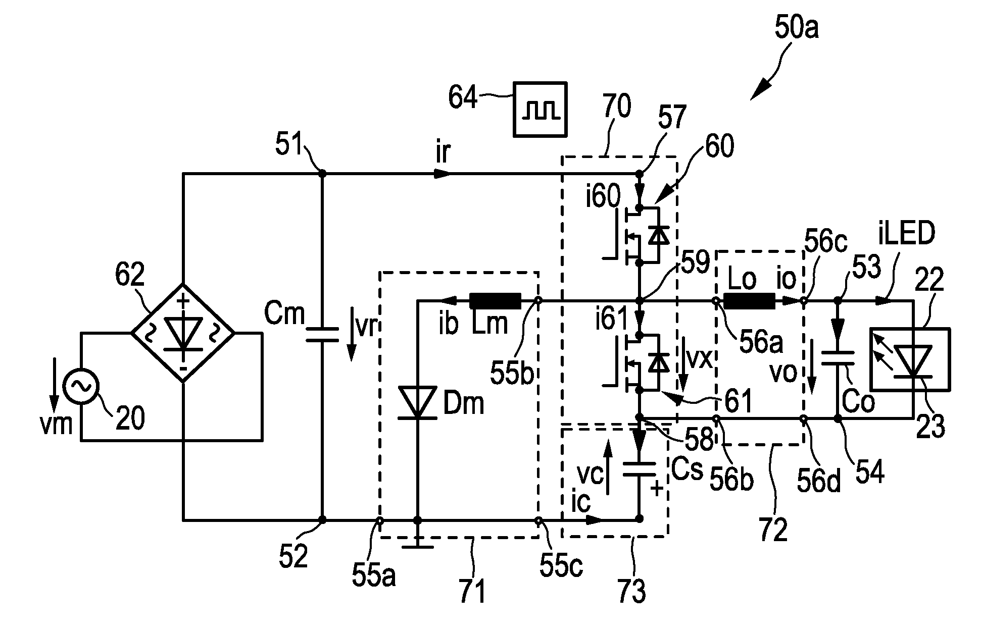
[0064]a driver device 50a according to the present invention is schematically shown in FIG. 3a. It comprises power input terminals 51, 52 for receiving a rectified supply voltage vr from an external power supply 20 (e.g. a mains voltage supply providing a mains voltage vm) which is preferably rectified by a rectifier 62. The driver device 50a further comprises power output terminals 53, 54 for providing a drive voltage vo and / or current io for driving a load 22.

[0065]A half bridge unit 70 (also called switching unit or half bridge) comprising a first 60 and second 61 switching element is coupled in series between a high voltage node 57 and a low voltage node 58 and forms a switch node 59 between said first and second switching elements 60, 61. A buck-boost input filter unit 71, comprising a first inductor Lm and a series diode Dm coupled in series to the first inductor Lm, is coupled between a power input terminal, here the low power input terminal 52 and said half bridge unit 70. A...

fourth embodiment

[0075]a driver device 50d according to the present invention is schematically shown in FIG. 4b. This embodiment is substantially identical to the embodiment of the driver device 50b, but also in this embodiment the position of load 22 (together with the output decoupling capacitor Co) is exchanged with the position of the energy storage unit 73. The energy storage unit is coupled to the output terminals 56c, 56d of the buck output filter unit 72. The high power output terminal 53 is coupled to the output terminal 55c of the buck-boost input filter unit 71 and the low power output terminal 54 is coupled to the low voltage node 58 of the half bridge unit 70.

[0076]Thus, according to the third and fourth embodiments the load 22 is connected at the output of the buck-boost converter (i.e. in parallel to Co and between the source electrode of the bottom switching element 61 and ground). The low frequency storage capacitor Cs is connected at the output of the buck converter (i.e. in series...

third embodiment

[0077]FIGS. 8 and 9 show signal diagrams of the third embodiment for an embodiment of a driver device 50c as shown in FIG. 4a during one mains cycle. For the example of the steady-state waveforms shown in FIG. 8 and the high-frequency waveforms at phase angle π / 2 from mains cycle shown in FIG. 9 the following values apply: vm=220 Veff, 50 Hz, 1 MHz switching frequency, Lm=200 μH, Lc=400 μH, Po=10 W, vo=400V, Cs=2 μF, PF=91%, THD=44%, maximum voltage stress across switches=711V. The term “av” refers to the average component over a switching cycle. d indicates the duty cycle.

[0078]The ZVS operation is shown in the high frequency switching waveforms of FIG. 9 for the case of π / 2 phase angle corresponding to the mains cycle. Capacitors Cm and Co filter these high switching frequency signals to prevent them at the input and output, respectively. The maximum voltage stress across the switches is the sum of both the rectified supply voltage and the load voltage.

[0079]As depicted in FIG. 8,...


PUM


Abstract

The present invention relates to a driver device (50a-50f) and a corresponding method for driving a load (22), in particular an LED unit comprising one or more LEDs (23). The proposed driver device comprises power input terminals (51, 52) for receiving a rectified supply voltage (vr) from an external power supply, power output terminals (53, 54) for providing a drive voltage and/or current for driving a load (22), a half bridge unit (70) comprising a first (60) and second (61) switching element coupled in series between a high voltage node (57) and a low voltage node (58) and having a switch node (59) between said first and second switching elements, a buck-boost input filter unit (71) comprising a first inductor (Lm) and a series diode (Dm) coupled between a power input terminal (51, 52) and said half bridge unit (70), a buck output filter unit (72) comprising a second inductor (Lo, Lc) coupled between said half bridge unit (70) and a power output terminal (53, 54), an energy storage unit (73), and a control unit (64) for controlling said switching elements (60, 61).

Description

FIELD OF THE INVENTION[0001]The present invention relates to driver device for driving a load, in particular an LED unit comprising one or more LEDs. Further, the present invention relates to a light apparatus.BACKGROUND OF THE INVENTION[0002]In the field of LED drivers for offline applications such as retrofit lamps, solutions are demanded to cope with high efficiency, high power density, long lifetime, high power factor and low cost, among other relevant features. While practically all existing solutions compromise one or the other requirement, it is essential that the proposed driver circuits properly condition the form of the mains power into the form required by the LEDs while keeping compliance with present and future power mains regulations. Of critical importance is to guarantee a maximum light perceptible flicker (preferably zero) at the same time that the power factor is maintained above a certain limit.[0003]Further, in off-line converters, energy from the power mains oft...

Claims


Application Information

Patent Timeline
Patent Type & Authority Applications(United States)
IPC IPC(8): H05B33/08H05B44/00
CPCH05B33/0809H02M3/158Y02B20/30H05B45/3725H05B45/375H05B45/39
Inventor ELFERICH, REINHOLDLOPEZ, TONI
Owner KONINKLIJKE PHILIPS ELECTRONICS NV
Why Eureka
Try Eureka