Electrical Powered Weight and Fullness Level System

a technology of electric power and fullness, applied in transmission systems, instruments, domestic applications, etc., can solve the problems of poor resource utilization, poor labor utilization, and poor risk for organizations and collection workers, so as to optimize the use of collection resources, reduce collection times, and efficiently use energy

Active Publication Date: 2014-05-08
DRATONX
View PDF36 Cites 42 Cited by
  • Summary
  • Abstract
  • Description
  • Claims
  • Application Information

AI Technical Summary

Benefits of technology

[0033]An advantage of the invention is that it provides a collection apparatus optimized for collection to reduce collection times.
[0034]Another advantage of the invention is that is provides a collection apparatus optimized to efficiently use energy, including solar energy.
[0035]Another advantage of the invention is that it provides a collection apparatus that may be used as part of a system to optimize the use of collection resources, such as collection workers, collection trucks, etc.
[0036]A further advantage of the invention is that it provides a collection apparatus the may be remotely monitored and controlled.
[0037]Yet a further advantage of the invention is that...

Problems solved by technology

In addition to the clear optimization issues caused by non-optimal collection schedules, the failure to collect the contents of collection apparatuses that have exceeded their capacity can create risks for organizations and collection workers, such as sanitation workers.
Collecting apparatuses below full capacity results in poor resource utilization, especially poor labor utilization, which is the most costly component of the collection process.
However, under existing collection processes, collection below apparatus capacity is often necessary to minimize the likeli...

Method used


Image

  • Electrical Powered Weight and Fullness Level System
  • Electrical Powered Weight and Fullness Level System
  • Electrical Powered Weight and Fullness Level System

Examples


Embodiment Construction

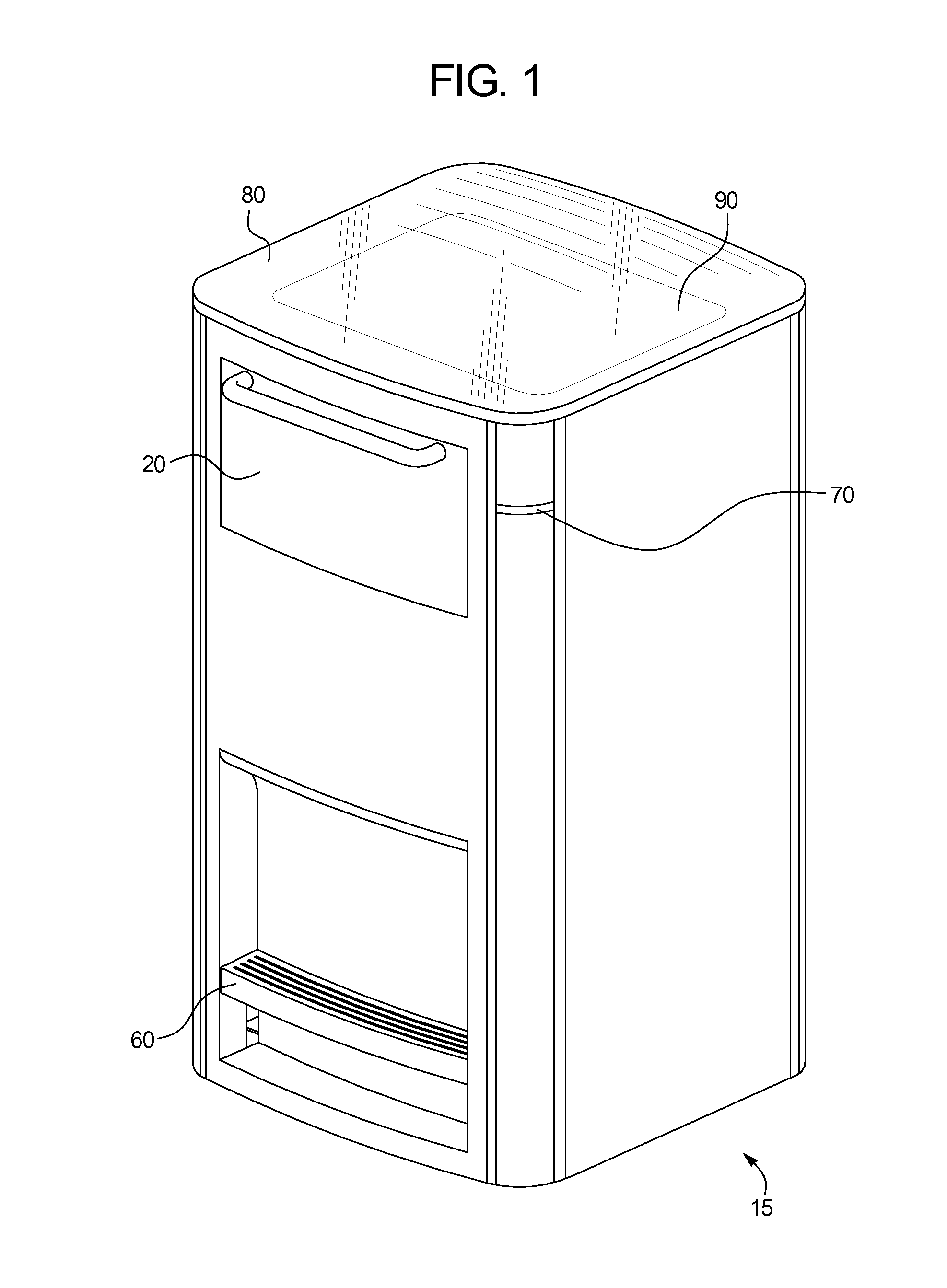
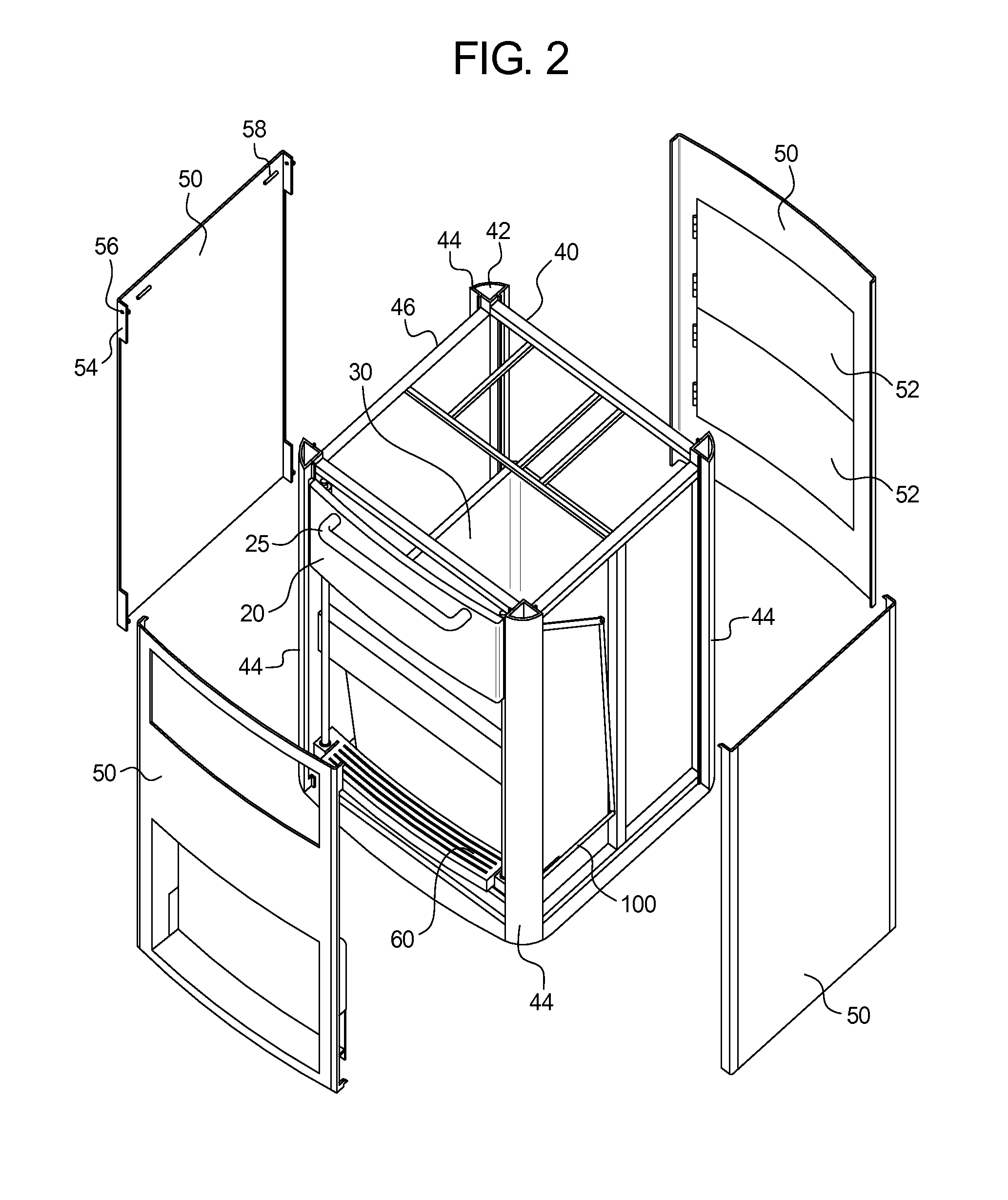
[0059]FIG. 1 illustrates an example of a collection apparatus 15. FIG. 2 illustrates an exploded view of the collection apparatus 15 to show its interior. As shown in FIG. 2, the collection apparatus 15 includes a deposit door 20 for receiving collected materials that fall into the collection bin 30. A foot pedal 60 may be included to permit a user to operate the deposit door 20 by foot. One or more indicators 70 may be provided to show the current state of the collection apparatus 15. The collection apparatus 15 may further include a compacting mechanism 400 (FIGS. 7a-9). The collection apparatus 15 may include a solar panel 90 mounted at the top or within the collection apparatus 15. The solar panel 90 may be protected from the elements by a cover 80, such as a clear, thermoformed polycarbonate. The solar panel 90 may be adjustable, either manually or electromechanically, to improve sun exposure. Collection and service doors 52 may be provided to permit access to the collected mat...


PUM


Abstract

A collection apparatus weight and fullness level reporting system includes: an inlet; a removable collection bin receiving material placed into the collection apparatus; a compacting mechanism including a ram body, wherein the ram body travels between a home position located above the collection bin to a maximum travel position located inside the collection bin, wherein during each compaction cycle the ram body travels along a variable length of the compaction path; a fullness-reporting module that determines the height of the material in the collection bin; and a controller that determines the length of the compaction path the ram body travels during each compaction cycle based on the input received from the fullness reporting module, wherein at the end of each compaction cycle in which the material height is below a maximum height, the ram body is brought to rest at a height below the home position.

Description

CROSS-REFERENCE TO RELATED APPLICATIONS[0001]This application claims the benefit of U.S. Provisional Application No. 61 / 722,177, filed on Nov. 4, 2012, the entirety of which is incorporated herein by reference.BACKGROUND OF THE INVENTION[0002]The present subject matter relates generally to collection apparatuses, such as waste collection units. More specifically, the present invention relates specifically to solar power collection apparatuses including an electrically powered weight and fullness level reporting systems.[0003]Collection apparatuses are used to collect materials such as waste, recycling, used cooking oil, clothing donations, and other unwanted materials for later collection and processing. Existing collection apparatuses are generally collected according to a schedule, regardless of the current level of fullness of the collection apparatuses. The fullness level itself is not apparent until after collection takes place. Accordingly, collection apparatuses are often col...

Claims


Application Information

Patent Timeline
IPC IPC(8): G08C17/02B65F1/14
CPCG08C17/02B65F1/1484B65F1/1405B65F1/141B65F1/1426B65F1/163B65F2210/108B65F2210/128B65F2210/1443B65F2210/148B65F2210/172B65F2210/184B30B1/24B30B9/321B30B9/3067B30B9/3007B30B9/3064
Inventor ULLRICH, JULIE ANNULLRICH, THOMAS ALBERT
Owner DRATONX
Why Eureka
Try Eureka