
System and method for reduced cache mode

a cache mode and cache technology, applied in the field of memory systems, can solve the problems of increasing power consumption, increasing power demand, and significant power consumption, and achieve the effects of reducing cache capacity, reducing cache utilization, and reducing cache memory

Inactive Publication Date: 2014-05-15
NVIDIA CORP
View PDF12 Cites 5 Cited by
  • Summary
  • Abstract
  • Description
  • Claims
  • Application Information

AI Technical Summary

Benefits of technology

This patent describes techniques for optimizing the use of memory in a computer system. By dynamically changing the memory configuration based on its utilization, the memory can be used more efficiently in various scenarios. For example, a large cache memory can be implemented to meet the needs of memory-intensive applications, but when cache utilization is reduced, the capacity of the cache can be reduced to save power. No longer needed memory locations are flushed of their data to prevent unknown data from being stored there. Overall, this patent offers a technology to make memory more flexible and efficient in computer systems.

Problems solved by technology

With larger memories, however, there is also increased power demand.
Especially in battery operated systems, power consumption is a significant issue.
In conventional systems, an important engineering tradeoff occurs when deciding on the size of a memory.
For example, in choosing the size of a cache, a larger memory can significantly improve performance but can also increase power consumption.
A more difficult situation is a system that can be expected to operate in varied environments with different levels of cache utilization.
In such situations, the systems are oftentimes limited to fixed cache memory sizes that may not be appropriate for all situations.

Method used


Image

  • System and method for reduced cache mode
  • System and method for reduced cache mode
  • System and method for reduced cache mode

Examples


Embodiment Construction

[0022]In the following description, numerous specific details are set forth to provide a more thorough understanding of the present invention. It will, however, be apparent to one of skill in the art that the present invention may be practiced without one or more of these specific details. In other instances, well-known features have not been described in order to avoid obscuring the present invention.

System Overview

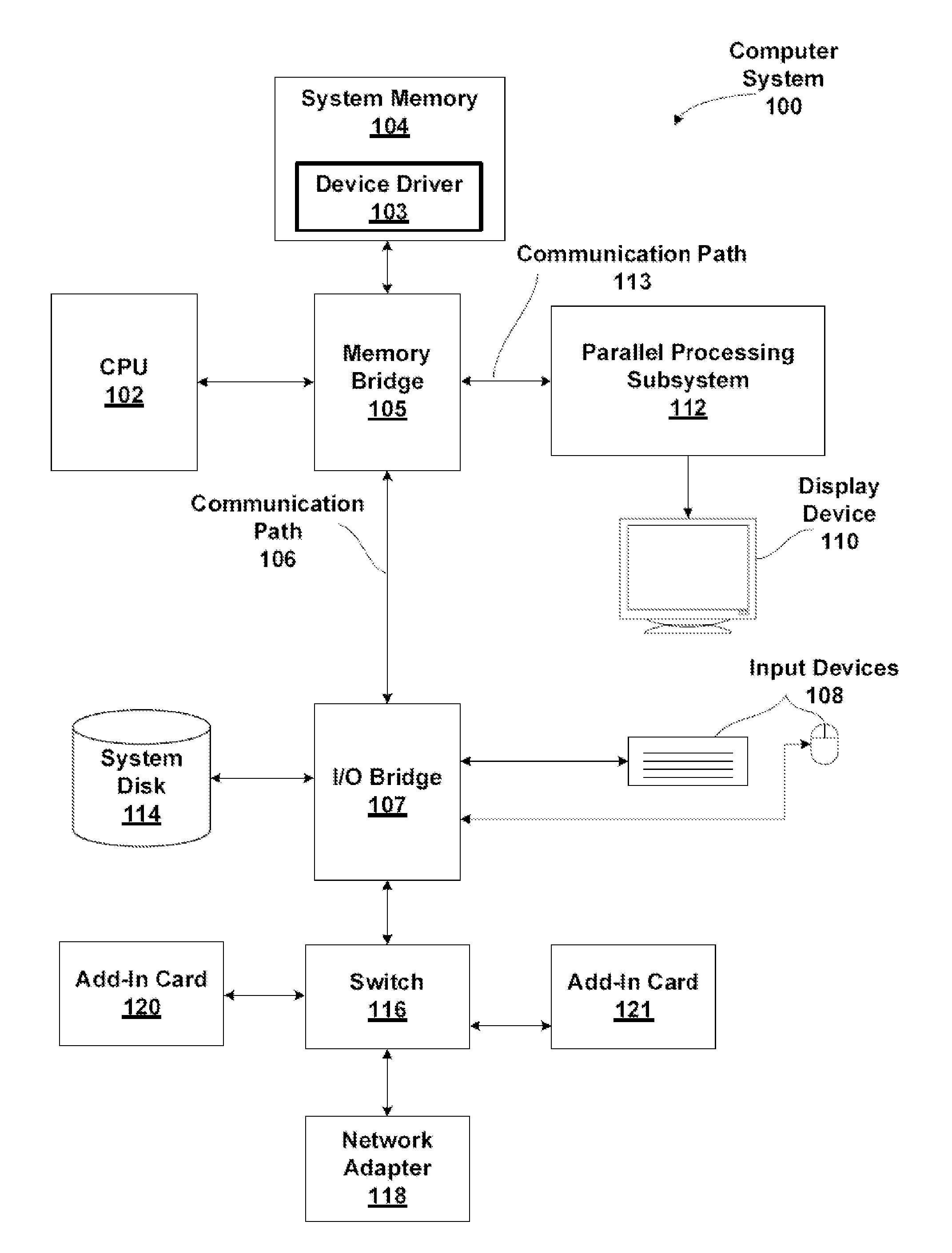
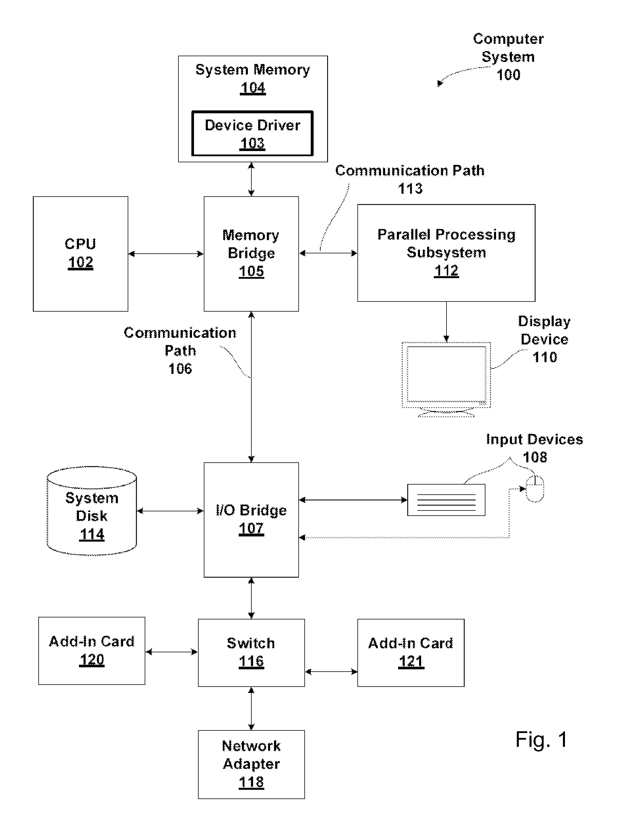
[0023]FIG. 1 is a block diagram illustrating a computer system 100 configured to implement one or more aspects of the present invention. Computer system 100 includes a central processing unit (CPU) 102 and a system memory 104 communicating via a bus path that may include a memory bridge 105. Memory bridge 105, which may be, e.g., a Northbridge chip, is connected via a bus or other communication path 106 (e.g., a HyperTransport link) to an I / O (input / output) bridge 107. I / O bridge 107, which may be, e.g., a Southbridge chip, receives user input from one or more user input...


PUM


Abstract

A system and method are described for dynamically changing the size of a computer memory such as level 2 cache as used in a graphics processing unit. In an embodiment, a relatively large cache memory can be implemented in a computing system so as to meet the needs of memory intensive applications. But where cache utilization is reduced, the capacity of the cache can be reduced. In this way, power consumption is reduced by powering down a portion of the cache.

Description

BACKGROUND OF THE INVENTION[0001]1. Field of the Invention[0002]The present invention generally relates to memory systems and more specifically to approaches for operating in a reduced cache mode.[0003]2. Description of the Related Art[0004]As computing power has increased, so too has the memory capacity of computing systems. Among the various types of memory, including RAM, ROM, cache, dynamic RAM, static RAM, Flash memory, virtual memory, graphics memory, and BIOS, each has increased in capacity as computer power and computer demands have increase.[0005]For example, through the years, the sizes of cache memories have increase. Benefits of larger cache memories include improving system performance. Generally, cache is used by computer processing unit to reduce the average time to access memory. Whereas accessing external dynamic RAM may introduce a relatively significant latency, accessing the more closely integrated cache can reduce latency. The cache is generally a smaller but fa...

Claims


Application Information

Patent Timeline
Patent Type & Authority Applications(United States)
IPC IPC(8): G06F12/08
CPCG06F12/0891G06F2212/601Y02D10/00
Inventor ROBERTSON, JAMES PATRICKRUBINSTEIN, ORENWOODMANSEE, MICHAEL A.BITTEL, DONLEW, STEPHEN D.RIEGELSBERGER, EDWARDSIMERAL, BRAD W.MUTHLER, GREGORY ALANBURGESS, JOHN MATTHEW
Owner NVIDIA CORP
Learn More