
Compensation system and liquid crystal display apparatus for liquid crystal panel

a liquid crystal display and liquid crystal panel technology, applied in the field of liquid crystal display (lcd) technology, can solve the problems of severe light leakage problem, large viewing angle light leakage in dark mode, and affect the contrast and sharpness at large viewing angles, so as to reduce light leakage, enlarge the viewing angle, contrast and sharpness

Inactive Publication Date: 2014-05-22
TCL CHINA STAR OPTOELECTRONICS TECH CO LTD
View PDF2 Cites 4 Cited by
  • Summary
  • Abstract
  • Description
  • Claims
  • Application Information

AI Technical Summary

Benefits of technology

The present invention is a system and a display that can effectively reduce light leakage in dark mode. This is achieved by using double-layered biaxial retardation films that have reasonable retardation values. This improves the contrast and sharpness at large viewing angles, which increases the viewing angle.

Problems solved by technology

If an unmatched retardation film is utilized with the liquid crystal display apparatus, not only does light leakage in dark mode occur at large viewing angles but also the contrast and sharpness at large viewing angles are affected.
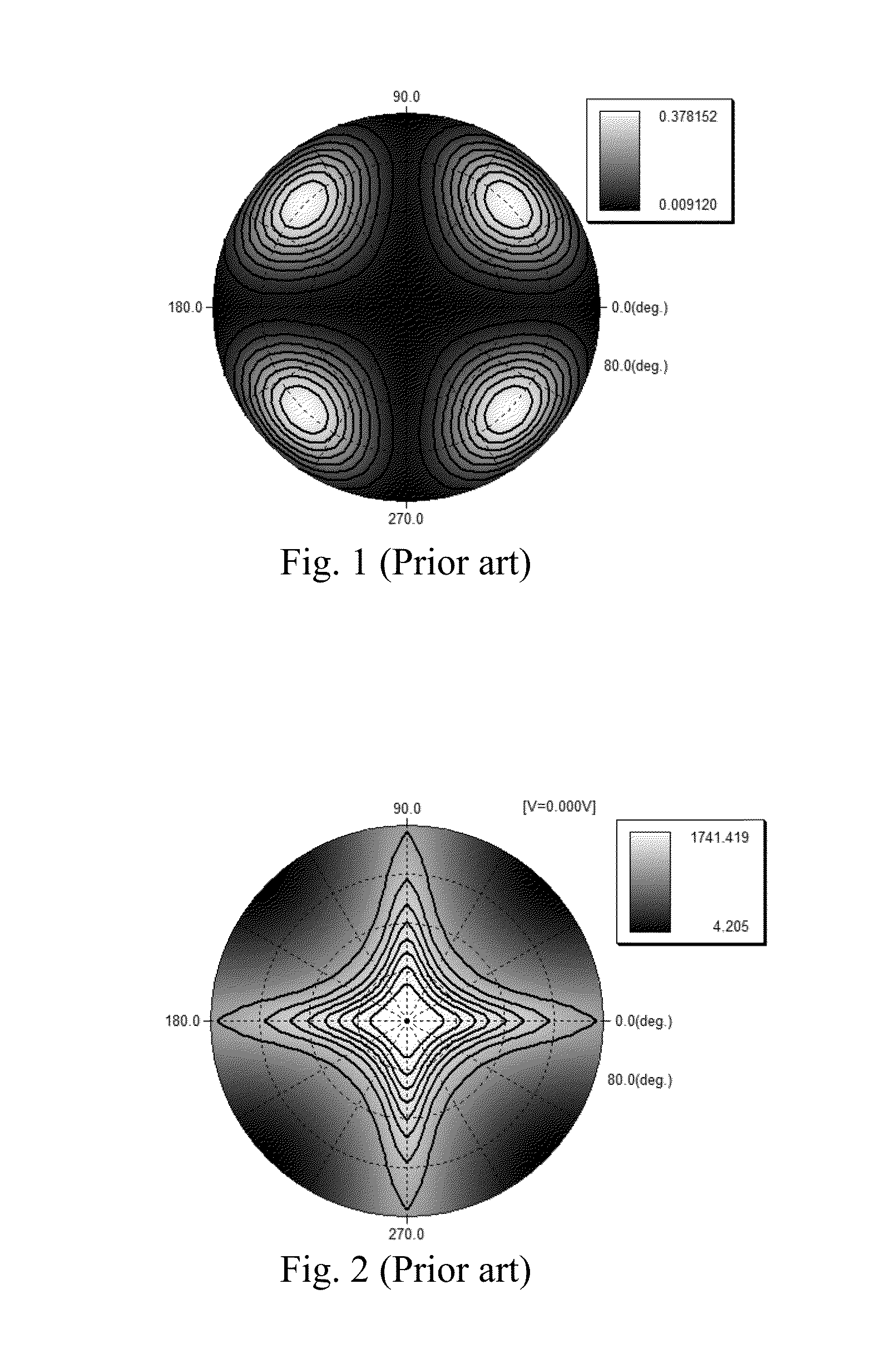
As can be seen from FIG. 1 and FIG. 2, under these circumstances there is severe light leakage problem in areas at azimuth angles between 30 degrees and 60 degrees, 120 degrees and 150 degrees, 210 degrees and 240 degrees, and 300 degrees and 330 degrees even after being compensated by the double-layered biaxial retardation film.

Method used


Image

  • Compensation system and liquid crystal display apparatus for liquid crystal panel
  • Compensation system and liquid crystal display apparatus for liquid crystal panel
  • Compensation system and liquid crystal display apparatus for liquid crystal panel

Examples


first embodiment

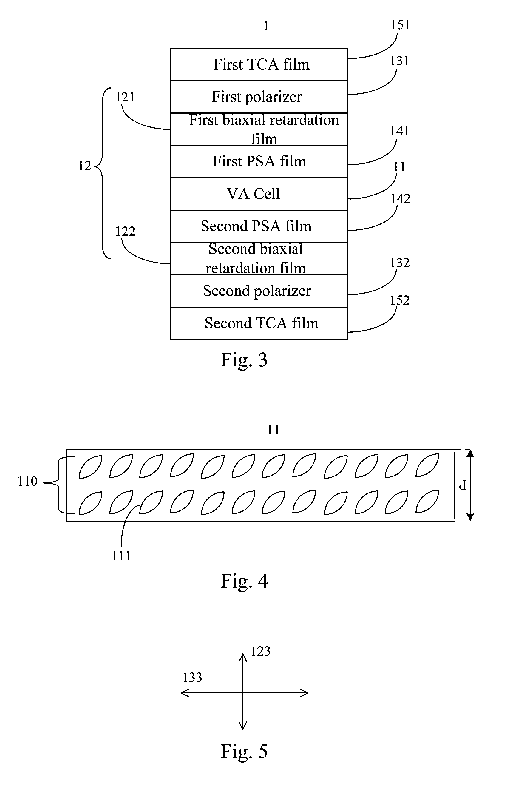
[0042]Please refer to FIG. 3, FIG. 3 is a schematic diagram showing a structure of a liquid crystal display apparatus according to the present invention. In the present embodiment, a liquid crystal display apparatus 1 comprises a liquid crystal panel 11, a compensation system 12, a first polarizer 131, a second polarizer 132, a first pressure sensitive adhesive (PSA) film 141, a second pressure sensitive adhesive film 142, a first three cellulose acetate (TCA) film 151, and a second three cellulose acetate film 152.

[0043]In the present invention, the liquid crystal panel 11 is a vertical alignment cell (VA cell). Please further refers to FIG. 4, FIG. 4 is schematic diagram showing a structure of the liquid crystal panel according to the first embodiment of the present invention. A liquid crystal layer 110 comprising a plurality of liquid crystal molecules 111 is disposed in the liquid crystal panel 11. The refractive index anisotropy of the liquid crystal layer 110 with respect to a...

second embodiment

[0050]The first biaxial retardation film 121 is usually the same as the second biaxial retardation film 122 in industrial production. In other words, the in-plane retardation values Ro1, Ro2 are the same, and the out-of-plane retardation values in the thickness directions Rth1, Rth2 are the same. It is therefore more convenient since there is no need to strictly distinguish between the first biaxial retardation film 121 and the second biaxial retardation film 122. In a second embodiment, reasonable ranges of retardation values are designed based on the fact that the in-plane retardation values of the first biaxial retardation film 121 and the second biaxial retardation film 122 Ro1, Ro2 are the same, and the out-of-plane retardation values in the thickness directions of the first biaxial retardation film 121 and the second biaxial retardation film 122 Rth1, Rth2 are the same.

[0051]Please refer to FIG. 9 and FIG. 10. FIG. 9 is a run chart showing a change of light leakage in dark mod...


PUM

PropertyMeasurementUnit
thicknessaaaaaaaaaa
optical path differenceaaaaaaaaaa

Abstract

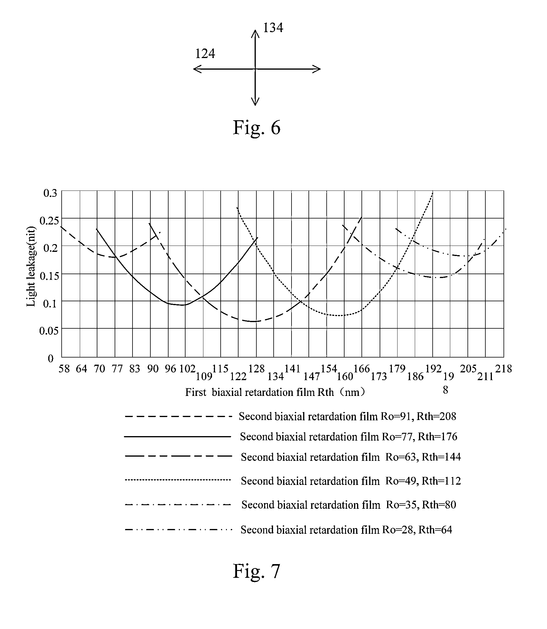
The present invention discloses a compensation system and a liquid crystal display apparatus used for a liquid crystal panel. The compensation system comprises a first biaxial retardation film and a second biaxial retardation film respectively disposed on either side of the liquid crystal panel. An in-plane retardation value of the first biaxial retardation film at a wavelength of 550 nm is Ro1. An out-of-plane retardation value in a thickness direction is Rth1. An in-plane retardation value of the second biaxial retardation film at the wavelength of 550 nm is Ro2. An out-of-plane retardation value in a thickness direction is Rth2. Wherein: 30.8 nm≦Ro1≦91 nm; 70.4 nm≦Rth1≦208 nm; 21 nm≦Ro2≦93.8 nm; Y1≦Rth2≦Y2; Y1=0.00424817×Rth12−1.9854256×Rth1+277.7: Y2=−0.003333×Rth12−0.033459×Rth1+234.2. The present invention effectively reduces light leakage of the liquid crystal panel in dark mode by disposing the double-layered biaxial retardation films having reasonable retardation values.

Description

BACKGROUND OF THE INVENTION[0001]1. Field of the Invention[0002]The present invention relates to a liquid crystal display (LCD) technology, more particularly, to a compensation system and a liquid crystal display apparatus for a liquid crystal panel.[0003]2. Description of the Related Art[0004]With the development of technology, a liquid crystal display apparatus has become the mainstream of the display apparatus. However, when the viewing angles of the liquid crystal display apparatus are enlarged, the contrast of pictures is reduced and the sharpness is lowered. The reason lies in that the birefringence of the liquid crystal molecules of the liquid crystal layer changes as a result of the change of the viewing angle. Light leakage of dark images is effectively reduced if a wide view film (WVF) is utilized. Hence, the contrast of pictures is significantly increased within a certain range of viewing angles. A retardation film, usually applied to a vertical alignment (VA) mode, mainl...

Claims


Application Information

Patent Timeline
Patent Type & Authority Applications(United States)
IPC IPC(8): G02F1/13363G02B5/30
CPCG02F1/1393G02F2413/03G02F1/133634G02F2413/02G02F2413/05G02F2413/12G02B5/3083
Inventor KANG, CHIH-TSUNGHAI, BO
Owner TCL CHINA STAR OPTOELECTRONICS TECH CO LTD
Learn More