
Method and apparatus for measuring the performance of antennas, mobile phones and other wireless terminals

Active Publication Date: 2014-05-22
BLUETEST
View PDF16 Cites 33 Cited by
  • Summary
  • Abstract
  • Description
  • Claims
  • Application Information

AI Technical Summary

Benefits of technology

The present invention aims to improve the accuracy of measurements using a specific type of measurement chamber. It does this by alleviating the uncertainty in the measurements, thereby allowing them to be performed faster, more accurately, and with better user interface and user controllability. This is important to avoid errors and user-induced uncertainties due to things like incorrect positioning of antennas or terminals. The invention provides a method and apparatus that addresses the shortcomings of existing systems.

Problems solved by technology

The above-mentioned procedure for measuring TIS is very time-consuming, both when it is performed in an anechoic chamber and in a reverberation chamber, because the sensitivity must be determined many times and averaged.
Also, it does not test how the terminal works when it is exposed to a continuous fading of the input signal, which is representative of an actual environment.
Preferably, the loading is not too strong, because then the resonances of the cavity modes disappear, and the chamber will no more have the desired function.
Unfortunately, such control by loading the chamber also affects the measurement uncertainty in a bad way.
However, this is only true at low frequencies.
When frequency increases the uncertainty does not improve accordingly, and is instead limited by a residual error that can be interpreted as direct coupling between the transmitting and receiving antennas or similar (P.-S.
However, the therein-disclosed solutions are all subject to similar problems in respect of measurement accuracy and the like.

Method used


Image

  • Method and apparatus for measuring the performance of antennas, mobile phones and other wireless terminals
  • Method and apparatus for measuring the performance of antennas, mobile phones and other wireless terminals
  • Method and apparatus for measuring the performance of antennas, mobile phones and other wireless terminals

Examples


Embodiment Construction

[0098]In the following detailed description, preferred embodiments of the present invention will be described. However, it is to be understood that features of the different embodiments are exchangeable between the embodiments and may be combined in different ways, unless anything else is specifically indicated. Even though in the following description, numerous specific details are set forth to provide a more thorough understanding of e present invention, it will be apparent to one skilled in the art that the present invention may be practiced without these specific details. In other instances, well-known constructions or functions are not described in detail, so as not to obscure the present invention.

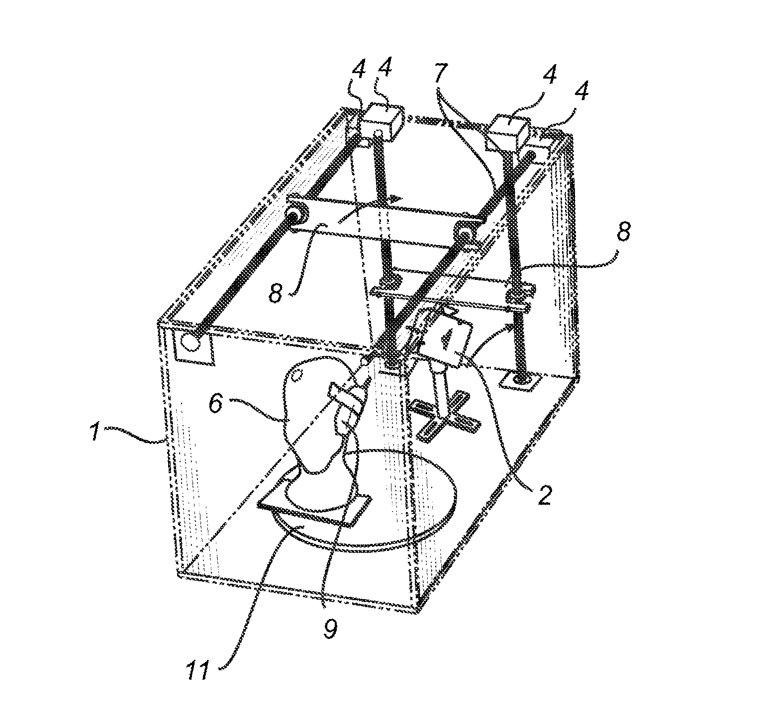
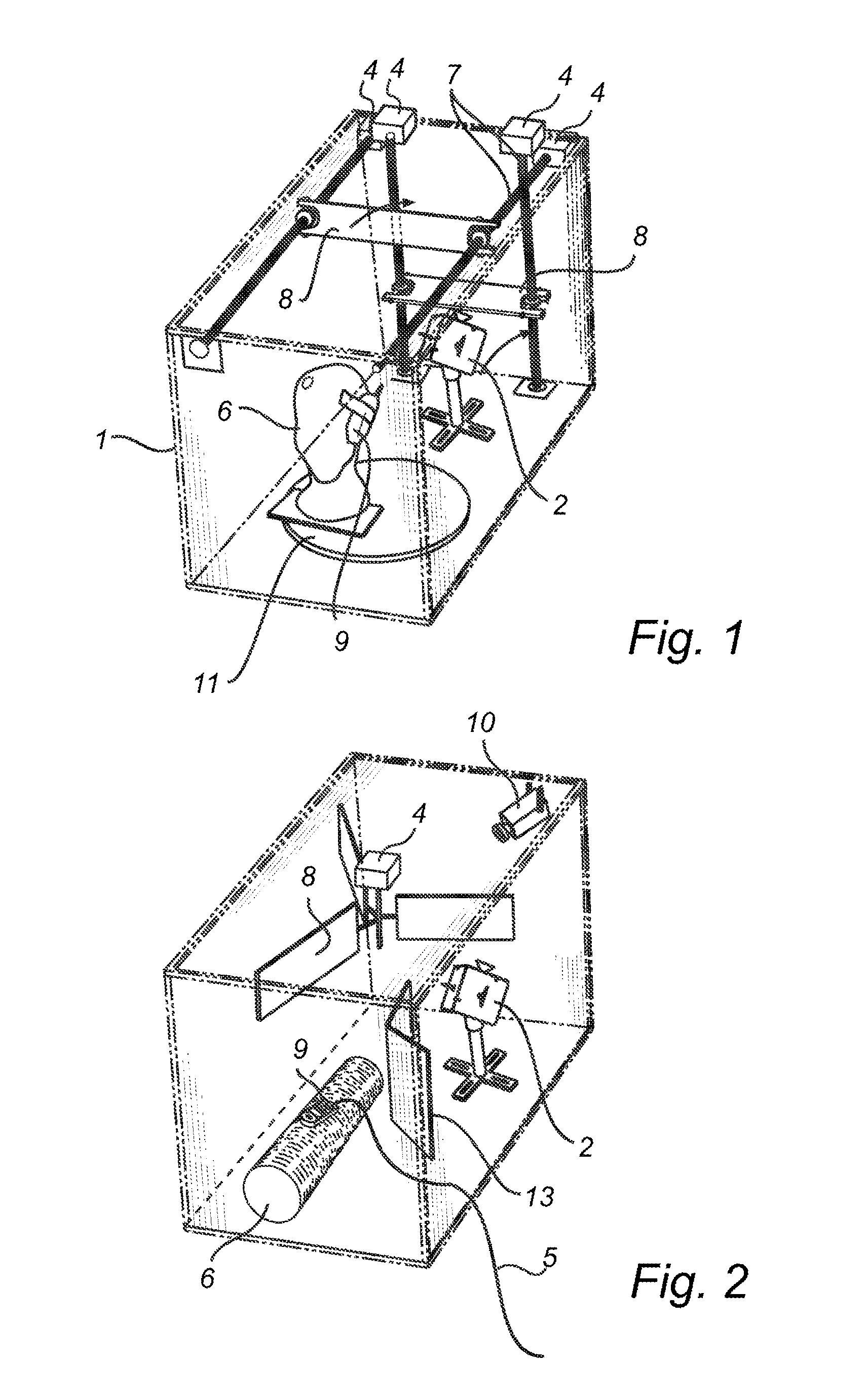
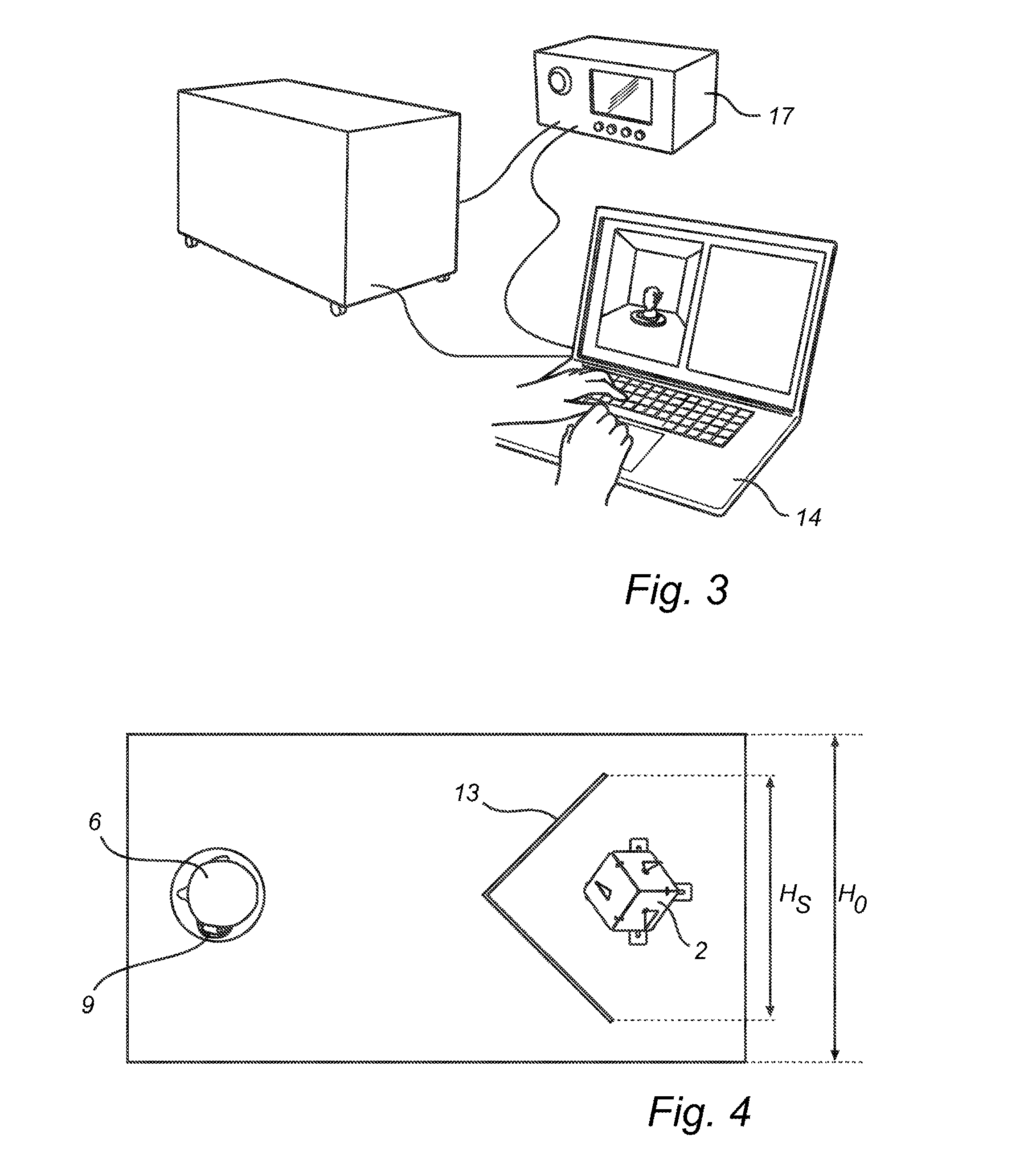
[0099]FIGS. 1 and 2 show two embodiments of an apparatus for measuring the performance of a device under test, such as antennas and mobile or wireless terminals, and specifically for antennas and terminals intended to be used in a multipath environment, according to a first embodimen...


PUM


Abstract

An apparatus including a chamber that defines an internal cavity therein, adapted to enclose the device under test, and including walls of an inwardly reflective material, rendering the walls reflective to electromagnetic waves, thereby simulating a multi-path environment. Thus, the chamber is a reverberation chamber. At least one moveable object and chamber antenna are arranged in the cavity. A measuring instrument is connected to the device under test and the chamber antenna, for measuring the transmission between them. Further, an improved antenna holder is disclosed, comprising three surfaces of a reflective material, said surfaces extending in planes which are orthogonal in relation to each other and each surface facing away from the other surfaces, and wherein a chamber antenna is arranged on each of said at least three surfaces. Other improvements relate to video surveillance, channel emulation and shielding.

Description

TECHNICAL FIELD OF THE INVENTION[0001]The present invention relates to an improved method and apparatus for measuring the performance of a device under test (DUT), and in particular antennas, mobile phones and other wireless terminals. More specifically, the present invention relates to improvements in measurements performed in a chamber defining an internal cavity therein, adapted to enclose the device under test, and including walls of an inwardly reflective material, rendering the walls reflective to electromagnetic waves, thereby simulating a multipath environment, and also comprising at least one moveable object within the cavity for obtaining a multitude of mode distributions and thereby making the DUT receive a signal that vary strongly with time, commonly referred to as fading. Such measurement chambers are referred to as reverberation chambers or mode-stirred or field-stirred chambers.BACKGROUND[0002]The reverberation chamber, or mode-stirred chamber, was before year 2000 o...

Claims


Application Information

Patent Timeline
IPC IPC(8): H04B17/00G01R29/08
CPCG01R29/0821G01R29/105H04B17/15G01R29/08
Inventor KILDAL, PER-SIMONORLENIUS, CHARLIE
Owner BLUETEST
Learn More