Magnetic device

a magnetic device and magnetic field technology, applied in the direction of magnetic device, basic electric element, electrical apparatus, etc., can solve problems such as performance degradation

Active Publication Date: 2014-05-29
IND TECH RES INST
View PDF1 Cites 6 Cited by
  • Summary
  • Abstract
  • Description
  • Claims
  • Application Information

AI Technical Summary

Problems solved by technology

One possible reason for the degraded performance is attributed to the damage on the film during manufacturing.
It was reported that even introducing a cap layer, such as silicon nitride, on the device right after the etching process would cause degradation.

Method used


Image

  • Magnetic device
  • Magnetic device
  • Magnetic device

Examples


Embodiment Construction

[0013]The embodiments of the present invention are described more fully hereinafter with reference to the accompanying drawings, which form a part hereof, and which show, by way of illustration, specific exemplary embodiments by which the invention may be practiced. This invention may, however, be embodied in many different forms and should not be construed as limited to the embodiments set forth herein; rather, these embodiments are provided so that this disclosure will be thorough and complete, and will fully convey the scope of the invention to those skilled in the art. As used herein, the term “or” is an inclusive “or” operator, and is equivalent to the term “and / or,” unless the context clearly dictates otherwise. In addition, throughout the specification, the meaning of “a,”“an,” and “the” include plural references. The term “coupled” implies that the elements may be directly connected together or may be coupled through one or more intervening elements.

[0014]The first embodimen...


PUM


Abstract

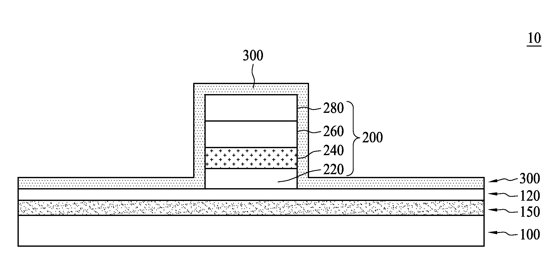
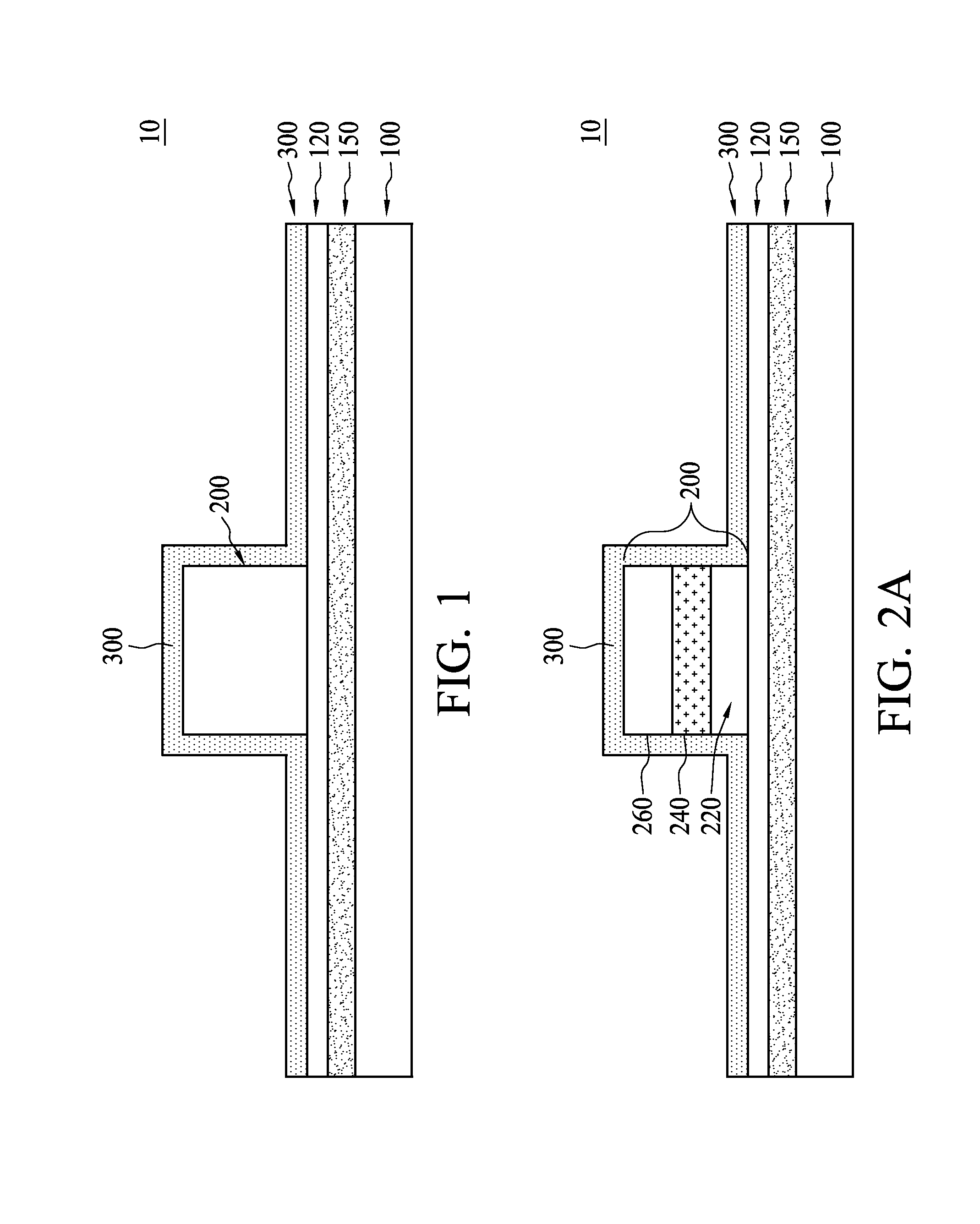
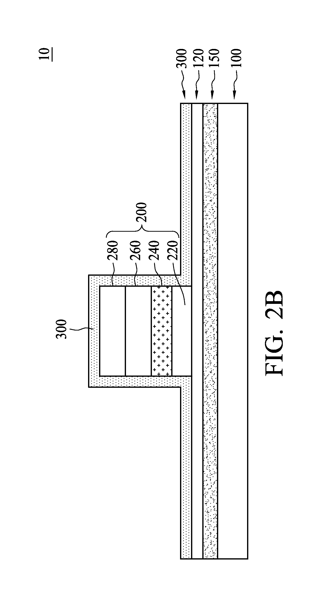
A magnetic device includes a substrate, a sensing block and a repair layer. The substrate has a registration layer and a barrier layer disposed on the registration layer. The sensing block is patterned to distribute on the barrier layer. The repair layer is disposed substantially on the barrier layer, wherein the barrier layer is configured to have a tunneling effect when a bias voltage exists between the sensing block and the registration layer.

Description

FIELD OF THE INVENTION[0001]The present disclosure generally relates to a magnetic device, and particularly to a memory storage device that uses a magnetic moment to store data.BACKGROUND[0002]Ferromagnetic material is utilized to manufacture a non-volatile memory device, such as magnetoresistive RAM (MRAM). Since its discovery in 1970, the tunneling effect of the magnetic tunnel junction (MTJ) has caused a dramatic change in the use of magnetic memory devices. The MTJ usually consists of at least three layers, which are the pinned layer, the barrier layer and the free layer. As a result, the stored memory in the domain can be written or read by sensing the current tunneling through the barrier.[0003]The correctivity or the ratio of the self spin-polarization is one of the major concerns regarding the efficiency and accuracy of when to read or write the memory storage domain. One possible reason for the degraded performance is attributed to the damage on the film during manufacturin...

Claims


Application Information

Patent Timeline
Patent Type & Authority Applications(United States)
IPC IPC(8): H01L29/82
CPCH01L29/82H10N50/10
Inventor CHIEN, CHENG WEISHEN, KUEI HUNGWANG, YUNG HUNG
Owner IND TECH RES INST
Why Eureka
Try Eureka