Capacitor Sensing Circuit

a sensing circuit and capacitor technology, applied in capacitance measurement, resistance/reactance/impedence, instruments, etc., can solve the problems of common mode and high time consumption of procedures, and achieve the effect of raising precision and sensibility

Inactive Publication Date: 2014-05-29
SENSORTEK TECH
View PDF6 Cites 6 Cited by
  • Summary
  • Abstract
  • Description
  • Claims
  • Application Information

AI Technical Summary

Benefits of technology

[0015]Therefore, the capacitor sensing circuit and differential integrator circuit thereof in the present invention could obtain the differential output signals related to the first capacitor and second capacitor to raise the precision and sensibility of the capacitor sensing circuit without affected by the common mode noise.

Problems solved by technology

Such procedures take much time.
Meanwhile, the accuracy of the sensed values is effected by the common mode noise.

Method used


Image

  • Capacitor Sensing Circuit
  • Capacitor Sensing Circuit
  • Capacitor Sensing Circuit

Examples


first embodiment

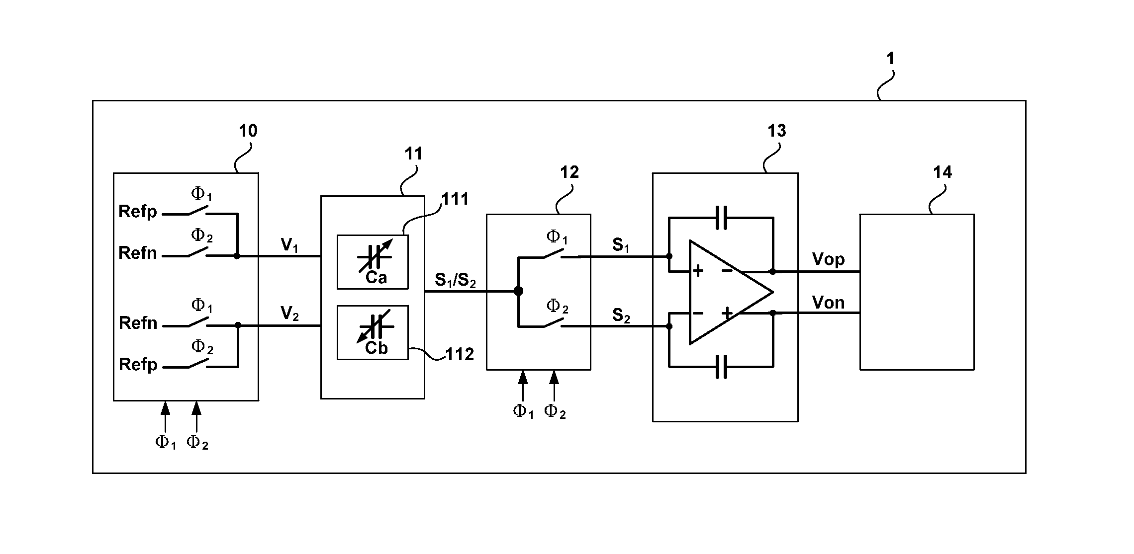
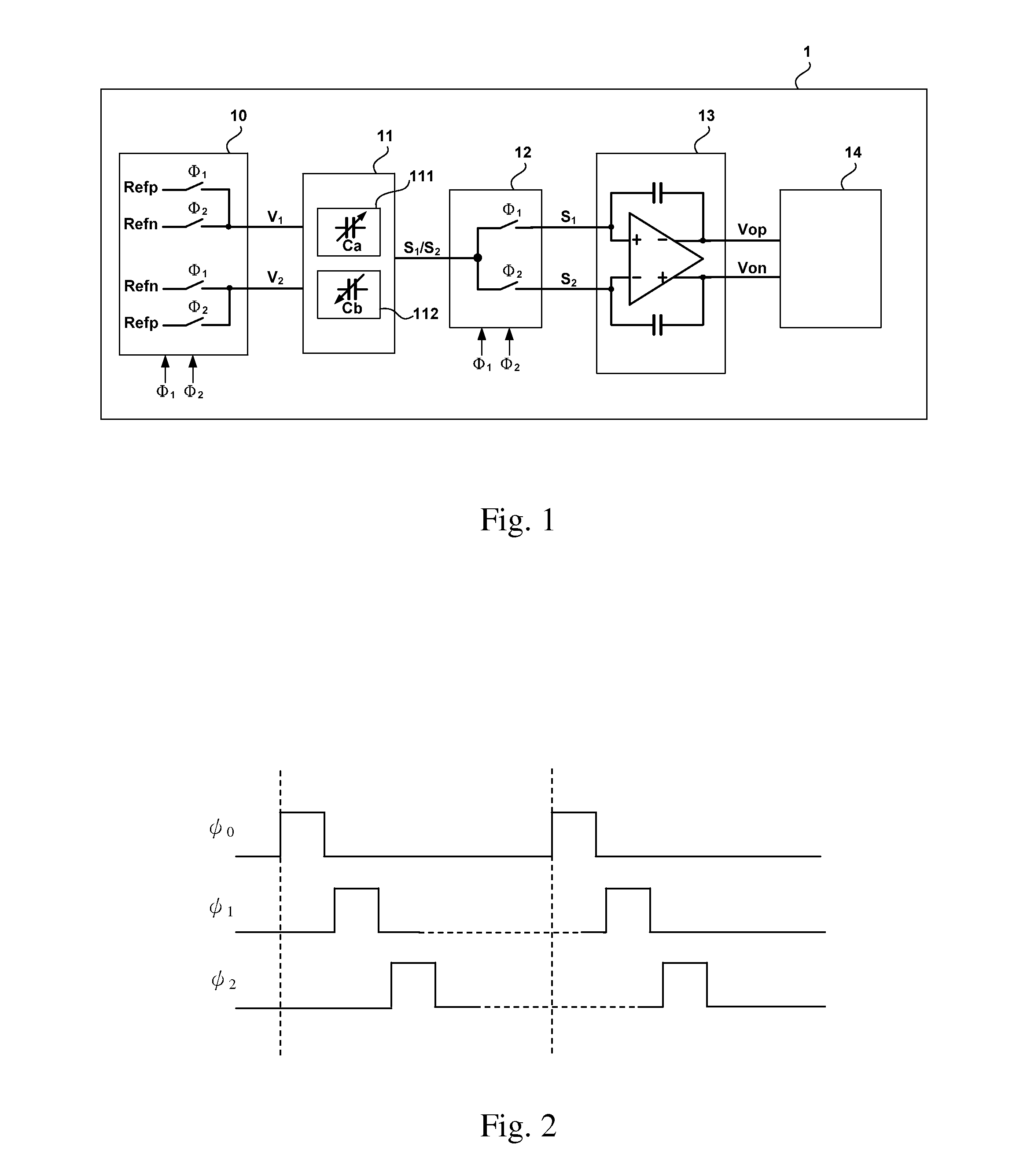
[0023]Please refer to FIG. 1, which shows a block diagram of a capacitor sensing circuit of a first embodiment according to the present invention. Here the capacitor sensing circuit 1 is not limited to any specific type. For example, the capacitor sensing circuit could be chosen from any of the types of single-transmitter, dual-transmitter, single-receiver, dual-receiver, or other multi-transmitter / receiver. The application of the capacitor sensing circuit 1 is for example but not limited to G-sensor, accelerometer, capacitive touch panel or the like. As shown in FIG. 1, here the capacitor sensing circuit 1 is of an exemplary dual-transmitter single-receiver type, comprising a driving unit 10, a capacitor sensing unit 11, a switching unit 12, a differential integrator circuit 13, and a post-processing circuit 14.

[0024]The driving unit 10 provides driving signals V1 and V2 required by the capacitor sensing unit 1 for generating voltage levels Refp and Refn for driving alternately thr...

second embodiment

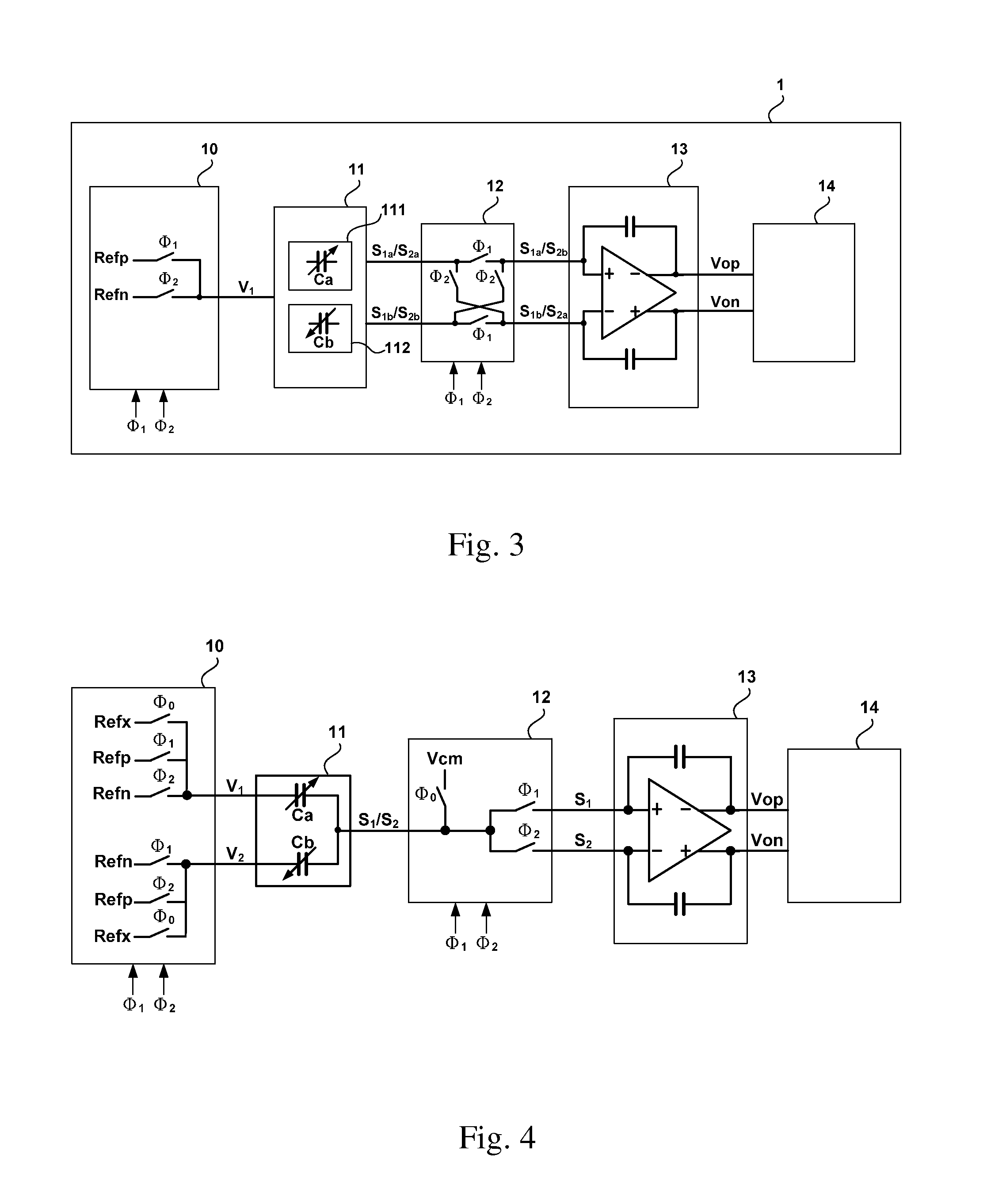
[0029]Please refer to FIG. 4, which shows a block diagram of a capacitor sensing circuit of a second embodiment according to the present invention. Here the capacitor sensing circuit is of a dual-transmitter single-receiver type with two routes inputting the reset timing signal φ0, first timing signal φ1, and second timing signal φ2 respectively and one single route outputting the first sensing signal S1 and second sensing signal S2. For clarifying the differences between the present and the previous embodiments, only the structural details of the capacitor sensing unit 11, switching unit 12 and differential integrator circuit 13 are shown.

[0030]When the level of the reset timing signal φ0 is high, the switching unit 12 switches correspondingly to reset the first capacitor and second capacitor to Vcm.

[0031]Then, when the level of the first timing signal φ1 is high, the capacitor sensing unit 11 outputs a first sensing signal S1 related to the difference between the capacitance of th...


PUM


Abstract

The present invention provides a capacitor sensing circuit, comprising a driving unit, a switching unit, a differential integrator circuit, and a post-processing circuit. The driving unit is for providing driving signals and timing required by the capacitor sensing circuit, the switching unit switches signals according to two inverting timings, φ1 and φ2, the driving unit drives the capacitor sensing circuit, and together with the positive/negative input terminals of the differential integrator circuit, the signals are accumulated and integrated in both timing φ1 and φ2. The post-processing circuit receive the differential output of the differential integrator circuit for processing and/or utilizing the signals. The two timing signals are time-sharing signals in a period. Therefore, the capacitor sensing circuit is not effected by the common mode noise, and the accuracy and the sensibility are increased.

Description

FIELD OF THE INVENTION[0001]The present invention generally relates to a capacitor sensing circuit, and more particularly, certain embodiments of the invention relate to a capacitor sensing circuit comprising a plurality of capacitors.BACKGROUND OF THE INVENTION[0002]According to the capacitance characteristic formula, the capacitance relates to the distance between the electrode plates, therefore, the major theory for implementing capacitor sensing is to link the physical distance with the capacitance. Nowadays, many circuits apply capacitor sensing therein, such as G-sensor, accelerometer, capacitive touch panel, etc. The sensed capacitance or capacitance variation is used for calculating the gravity, accelerometer, or determining pressing.[0003]Generally, most of the circuits applying capacitor sensing configure several capacitors for multi-dimensional sensing to identify the variation of the physical distance on each dimension, such as at least one capacitor for sensing the vari...

Claims


Application Information

Patent Timeline
Patent Type & Authority Applications(United States)
IPC IPC(8): G01R27/26
CPCG01R27/2605G01D5/24
Inventor LIN, MENG YONGLIU, MING-HUANGOU, WEI YANG
Owner SENSORTEK TECH
Why Eureka
Try Eureka