Light and bioelectric therapy pad

a bioelectric and electrode technology, applied in the field of light and bioelectric electrodes, can solve the problems of lack of electronic stimulation, lack of chromophores, and low current current level, and achieve the effects of flexibility, heat management, and final thinness of the therapy electrod

Active Publication Date: 2014-05-29
POINT SOURCE
View PDF15 Cites 32 Cited by
  • Summary
  • Abstract
  • Description
  • Claims
  • Application Information

AI Technical Summary

Benefits of technology

[0018]Yet another aspect of the present invention is the use of reverse mount LED to achieve ultimate thinness, smoothness, thermal management, and flexibility of the therapy pad.

Problems solved by technology

This presents numerous technical weaknesses, including the potential deleterious effects of temperature on the level of current, the potential build up higher impedance material on the electrodes that can affect the level of current, the discharge of the electrodes over time (they are batteries), and the effect of any changes in “wetting” of the electrodes that affects the level of current.
Weaknesses of low-level light therapy are a lack of electronic stimulation and the dependence on stimulating chromophores.
Conventional light therapy devices typical have limited and / or poor control of the light dosage.
The delivery of light to the wound site is typically cumbersome when using conventional light therapy devices in the form of wands, screens, helmets, etc.
These disclosed light therapy pads each suffer from one or more of the following: inadequate control of light dosage, impractical means of controlling potential heat buildup between the light therapy pad and the treated tissue; limited flexibility; lack of a smooth pad surface for contacting the skin; mis-shaped to match a specific anatomical site to achieve a specific therapeutic outcome; and lack of a simple and practical means of attaching the light pad to the desired anatomical site.

Method used


Image

  • Light and bioelectric therapy pad
  • Light and bioelectric therapy pad
  • Light and bioelectric therapy pad

Examples


Embodiment Construction

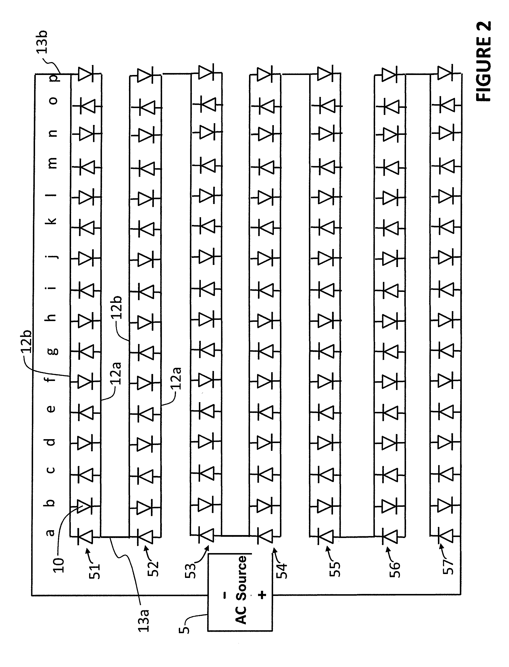
[0045]The present invention employs independently, and in combination, the principles of unidirectional current flow in the forward direction through a diode, and Ampere's law of magnetic fields from current through a wire.

[0046]Current flows through a diode in the forward direction, from the anode terminal of the diode toward the cathode terminal of the diode. Current supplied at the anode terminal will flow through the diode. Current supplied at the cathode terminal will not flow through the diode.

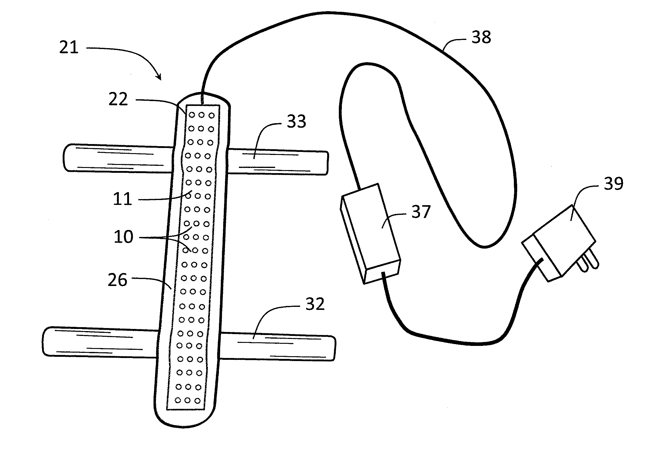
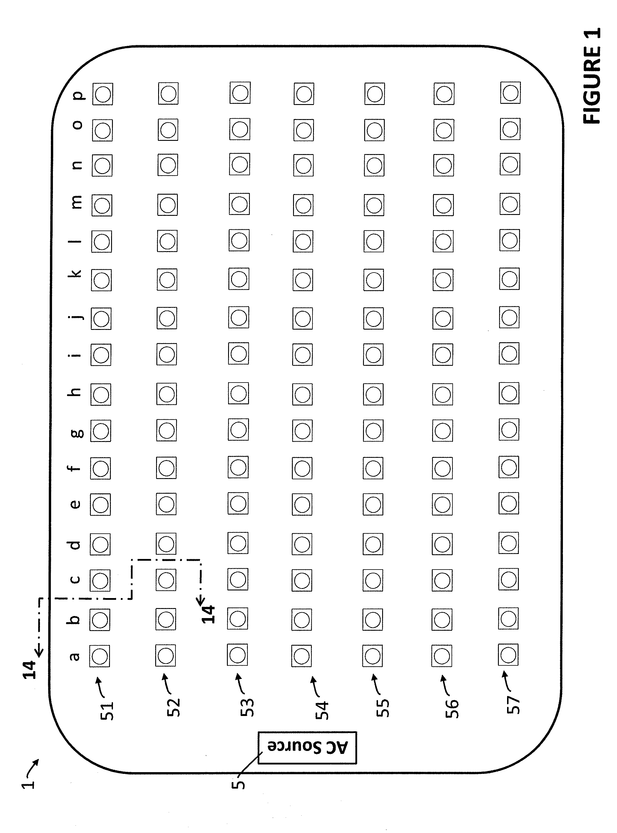
[0047]The present invention provides a circuit comprising a plurality of diodes that are arranged and wired into an “approximate linear tracing” that provides a bioelectric therapy tracing. The plurality of diodes, typically light emitting diodes (LEDs), which also provide a source of light when current flows in the forward direction through the LED, are arranged in a row, and each LED in the row is wired in parallel with the other LEDs between a first header tracing and a second header ...


PUM


Abstract

A light and bioelectric therapy pad that delivers light and bioelectric stimulation to adjacent tissue. The therapy pad includes an electrical tracing circuit containing elongated, parallel and spaced-apart approximate linear tracings (ALT) that provide current flow in opposite directions along the ALT during alternating positive and negative drive cycles of an alternating current (AC) supply. The ALT includes first and second header tracings wired to a row of light emitting diodes (LEDs), with the anodes of a first group of LEDs wired to the first header tracing, and the anodes of the remaining LEDs wired to the second header tracing. The ALTs are wired into the circuit with current flowing to the first header tracing at one end of the row of LEDs, and to the second header tracing at the opposite end, so that adjacent ALT provide current flow in opposite directions during both positive and negative drive cycles.

Description

CROSS-REFERENCE TO RELATED APPLICATION[0001]This application claims the benefit of U.S. Provisional Application No. 61 / 730,653, filed on Nov. 28, 2012, the disclosure of which is incorporated herein by reference.FIELD OF THE INVENTION[0002]The present invention relates to light- and bioelectric-emitting pads for therapeutic methods.BACKGROUND OF THE INVENTION[0003]Two modalities to enhance wound healing that have been disclosed in the art are low level light therapy (LLLT) and bioelectric therapy. Each of these modalities has individually shown value in accelerating the healing of wounds. Low level light therapy utilizes light in the 600 to 1000 nm wavelength band to stimulate the biological healing process. Bioelectric therapy provides a device in direct contact with a bodily fluid to drive a small, constant and direct current of 1 to 10 microamps in the conductive bodily fluids of the wound to similarly stimulate wound healing. A recent bioelectric stimulation article with referen...

Claims


Application Information

Patent Timeline
Patent Type & Authority Applications(United States)
IPC IPC(8): A61N1/36A61N5/06
CPCA61N1/0476A61N1/0492A61N1/326A61N1/36034A61N5/0613A61N2005/0645A61N2005/0652
Inventor MERSCH, STEVEN H.
Owner POINT SOURCE
Why Eureka
Try Eureka