
Hybrid Work Vehicle

a hybrid work and vehicle technology, applied in vehicle position/course/altitude control, process and machine control, instruments, etc., can solve the problem of difficult application of motor assistance technology used in hybrid work vehicles to motor assistance in such constant-speed control, and achieve the effect of optimal suppression of battery consumption

Active Publication Date: 2014-05-29
KUBOTA LTD
View PDF24 Cites 36 Cited by
  • Summary
  • Abstract
  • Description
  • Claims
  • Application Information

AI Technical Summary

Benefits of technology

The present invention provides a hybrid work vehicle that can use an internal combustion engine and a battery for working with an appropriate work implement, while preventing the battery from getting flat. This is achieved through a control of the electric-hydraulic pump in the hydraulic vehicle operation device which optimally suppresses battery consumption. This invention is especially useful for vehicles that are strictly restricted on battery consumption, such as electrically-driven vehicles where the battery is also used as a running-drive motor generator.

Problems solved by technology

In particular, constant-speed control for maintaining a constant number of engine revolutions is essential in a work vehicle such as a tractor for cultivating the land, and it is difficult to apply the motor assistance technology used in a hybrid work vehicle to motor assistance in such constant-speed control.

Method used


Image

  • Hybrid Work Vehicle
  • Hybrid Work Vehicle
  • Hybrid Work Vehicle

Examples


first embodiment

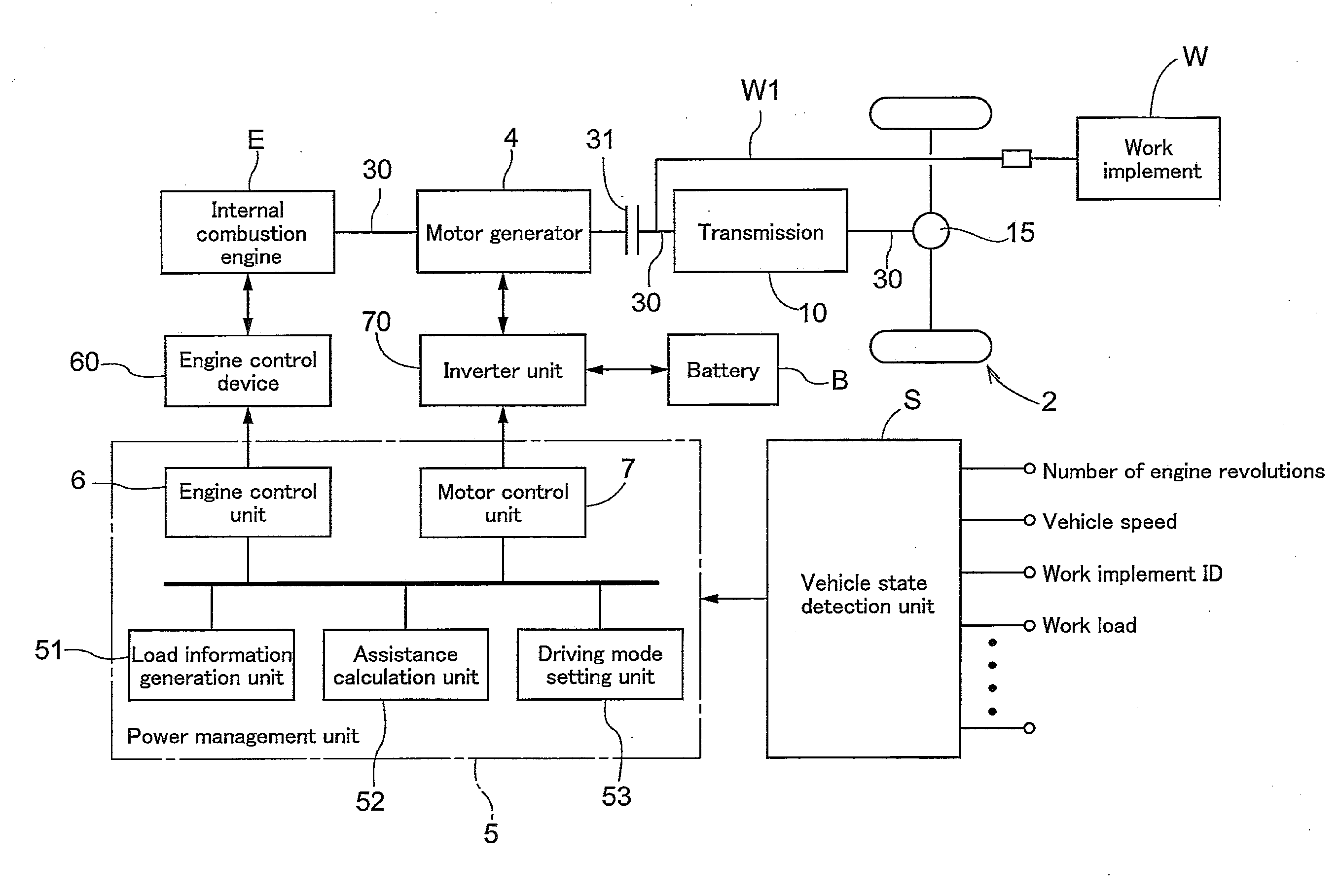
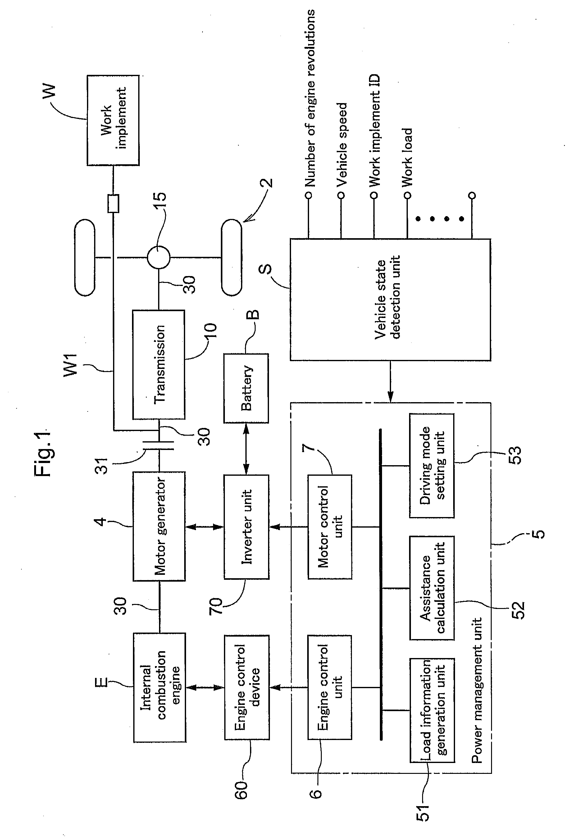
[0051]Prior to a detailed description of a first embodiment of the present invention, a basic configuration of a power system employed in the first embodiment will be described using FIG. 1.

[0052]This hybrid work vehicle is provided with an internal combustion engine E and a motor generator 4 as driving sources, and performs a running work using a work implement W mounted in the vehicle body while running with a running device 2 constituted by wheels or a crawler. A power transmission system for transmitting power from power reduction includes a clutch 31 for turning on / off transmission of power from the driving sources, a PTO shaft W1 for transmitting power to the work implement W, and a transmission shaft 30 for transmitting power to the running device 2. A transmission 10 provided with a transmission mechanism is constructed on the transmission shaft 30.

[0053]The motor generator 4, to which power is supplied from a battery B, generates rotational power and cooperates with the int...

second embodiment

[0087]Prior to a detailed description of a second embodiment of the present invention, a basic configuration of a power system employed in the second embodiment will be described using FIG. 10. Note that the basic configuration of this power system is similar to the basic configuration of the power system in FIG. 1, and the description using FIG. 1 should be referred to for the details not described here.

[0088]This hybrid work vehicle is provided with an internal combustion engine E and a motor generator 4 as driving sources, and performs a running work using a work implement W mounted in the vehicle body while running with a running device 2 constituted by wheels or a crawler. A power transmission system for transmitting power from a driving sources includes a main clutch 31 for turning on / off transmission of power from the driving sources, a PTO shaft W1 for transmitting power to the work implement W, and a transmission shaft 30 for transmitting power to the running device 2. A tr...

third embodiment

[0110]Prior to a detailed description of a third embodiment of the present invention, a basic configuration of a hydraulic vehicle operation device employed in the third embodiment will be described using FIG. 11. Note that the basic configuration of this hydraulic vehicle operation device includes the basic configuration of the power system shown in FIG. 1 or FIG. 6, and the above description should be referred to for the details not described here. Note that the vehicle shown as an example in FIG. 11 is a hybrid work vehicle, and a power-steering device 9 is dealt with as the hydraulic vehicle operation device.

[0111]The power-steering device 9 is provided with a steering wheel 21 disposed above a handle post 22, and a power-steering hydraulic circuit 90 for changing a steering angle of a steering control wheel 2a based on an input, which is a steering operation of the steering wheel 21. The power-steering hydraulic circuit 90 includes a power-steering hydraulic control unit 91 fun...


PUM


Abstract

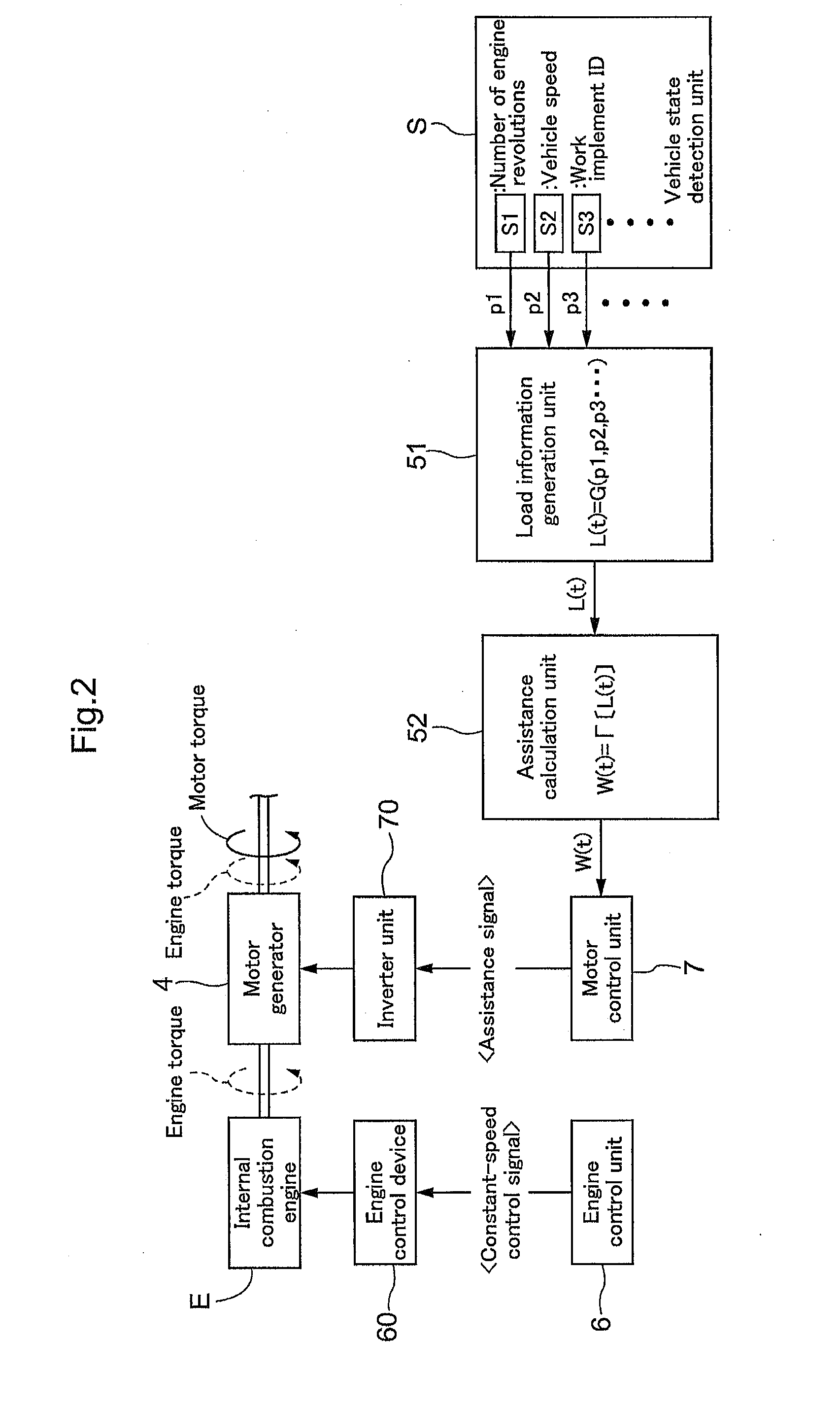
A hybrid work vehicle is provided with an internal combustion engine for supplying driving force to a running device and a work implement via a transmission shaft, a motor generator for assisting the internal combustion engine by outputting power to the transmission shaft, and a battery for receiving charging electricity from the motor generator and giving driving electricity to the motor generator. A load information generation unit generates load information indicating a rotational load received by the internal combustion engine when in a constant-speed control mode for maintaining a constant number of revolutions of the internal combustion engine, based on an input parameter, and an assistance calculation unit calculates an amount of assistance for internal combustion engine by the motor generator, based on the load information when in the constant-speed control mode.

Description

TECHNICAL FIELD[0001]The present invention relates to a hybrid work vehicle including an internal combustion engine and a battery charged by the internal combustion engine, more particularly to a hybrid work vehicle including a power source using an internal combustion engine and a motor generator, the internal combustion engine being assisted by the motor generator.BACKGROUND ART[0002]With a hybrid work vehicle in which a motor generator assists an internal combustion engine, the vehicle is caused to run with power supplied from the internal combustion engine, and the motor generator is operated as a motor in accordance with running conditions (vehicle speed, amount of operation of an accelerator pedal (accelerator opening), operation state of internal combustion engine, state of running road surface, gear position, remaining battery capacity, etc.), and the running of the vehicle is assisted with power that is output from the motor generator. Also, this motor generator can be oper...

Claims


Application Information

Patent Timeline
IPC IPC(8): B60W20/00B60W10/08B60W10/06
CPCB60K6/485B60W10/06B60W10/08B60W40/105B60W2710/08B60W2510/244B60W2520/10B60W2510/0638B60W2510/0657B60W2300/15B60W2710/0644B60W2710/083B60Y2200/411B60W10/02B60W20/19B60W2300/152Y10S903/93Y02T10/62B60W20/10
Inventor NISHI, KEISHIROHANA, HIDETOSHISHINKAI, ATSUSHIMUKAI, HISAOKONO, MICHITAMATSUZAKI, YUSHIFUJIMOTO, YOSHITOMOUMEMOTO, SUSUMUHAYASHI, SHIGEKIOBATA, NORIOKAWAMOTO, TOSHIKAZUICHIKAWA, NOBUSHIGE
Owner KUBOTA LTD
Learn More