Electromagnetic actuator having improved force density and use therof for an electric razor

Active Publication Date: 2014-06-05
MOVING MAGNET TECH
View PDF15 Cites 3 Cited by
  • Summary
  • Abstract
  • Description
  • Claims
  • Application Information

AI Technical Summary

Benefits of technology

[0013]Patent EP1005714 is also known in the prior art, which discloses a magnetic actuator the basic pattern of which is identical and which is composed of a two-pole stator and one or two movable portion(s) having 3 alternate magnets. The invention provides for the modification of the magnetic structure of the actuator disclosed in patent EP1005714 by increasing the force factor thereof in the same volume, without modifying the intrinsic characteristics thereof which are the coil volume and permeance. It is thus possible to produce, according to the invention, an actuator the volume of which is substantially less than the volume which would be required by an actuator produced according to the teachings of the patent EP1005714 to develop a force having the same intensity.
[0014]Adding a mild ferromagnetic yoke makes it possi

Problems solved by technology

This solution has a drawback in that the force density enabling a satisfactory operation requires a structure with large dimensions.
When the geometric dimensions are reduced into a compact configuration, and more particularly the thickness of the structure, this results in situations wherein the force density is insufficient.
Such devices of the prior art may be inefficient when the need for a significant miniaturization of the actuator exists.
The devices of patents EP0592647 and EP1005714 thus develop too low force factors (force per ampere-turn), which makes the utilization thereof non viable with small dimensions, since heating is too important.
Such more important electric power will result in too high current consumption, thus li

Method used


Image

  • Electromagnetic actuator having improved force density and use therof for an electric razor
  • Electromagnetic actuator having improved force density and use therof for an electric razor
  • Electromagnetic actuator having improved force density and use therof for an electric razor

Examples


Embodiment Construction

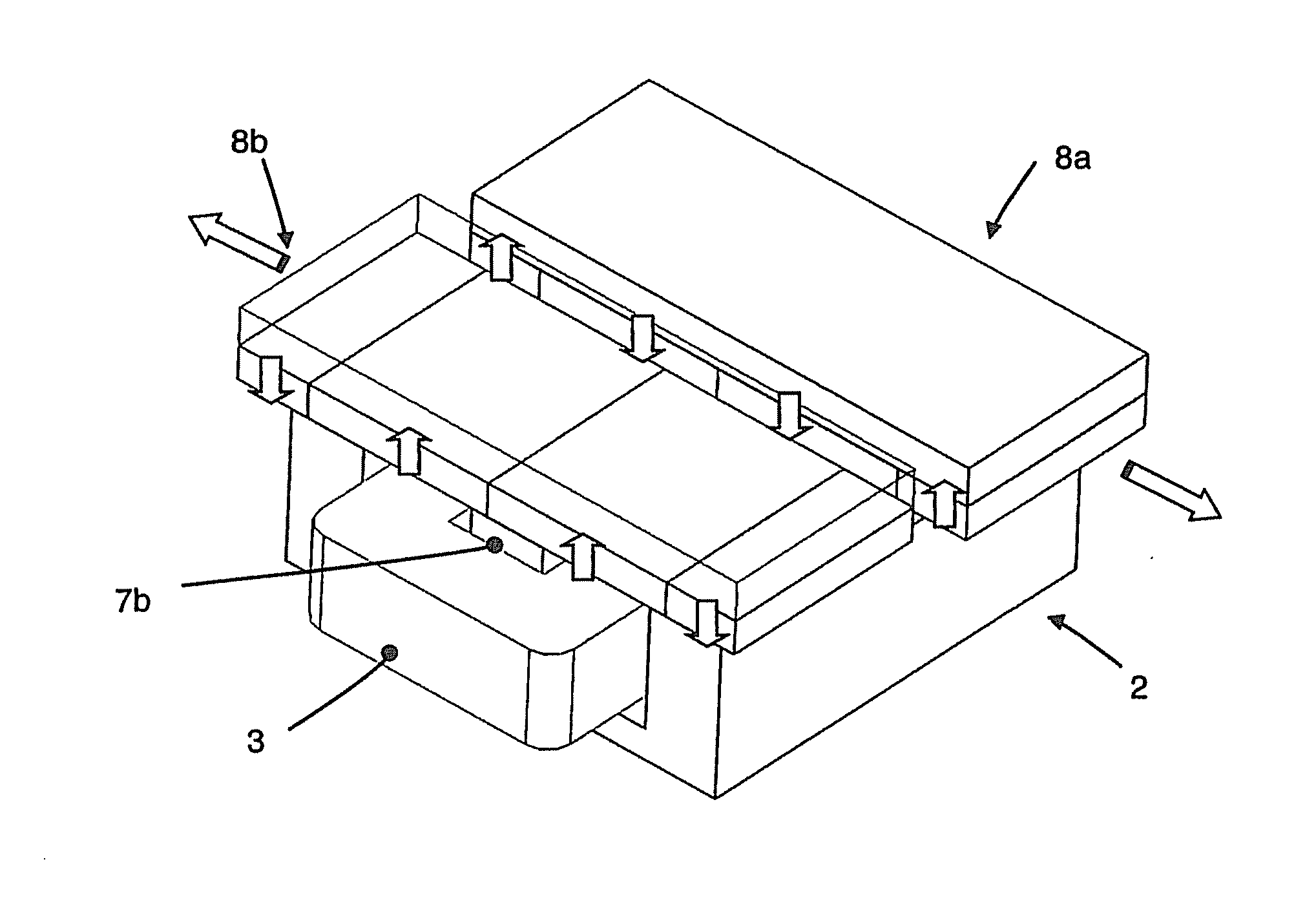
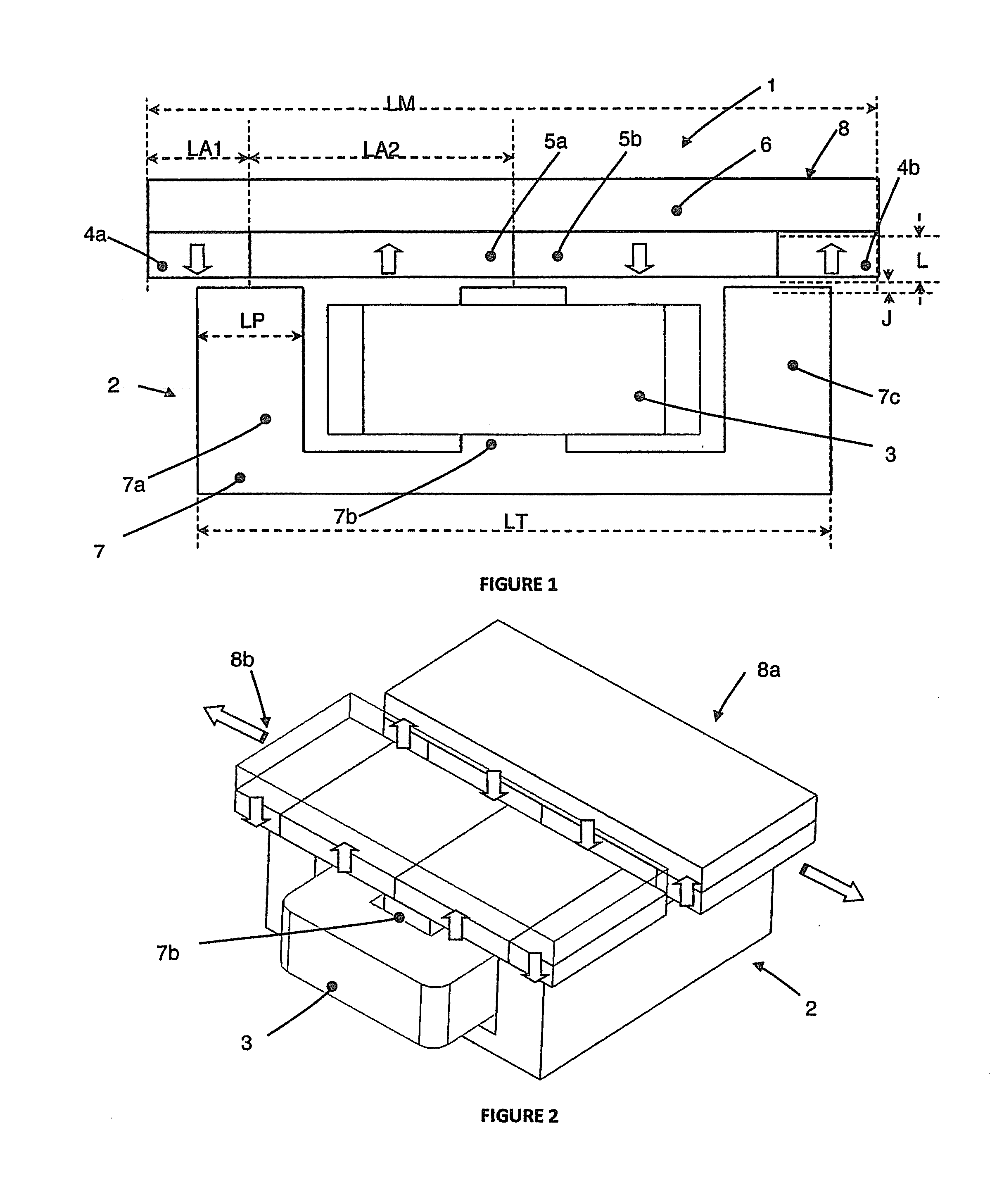
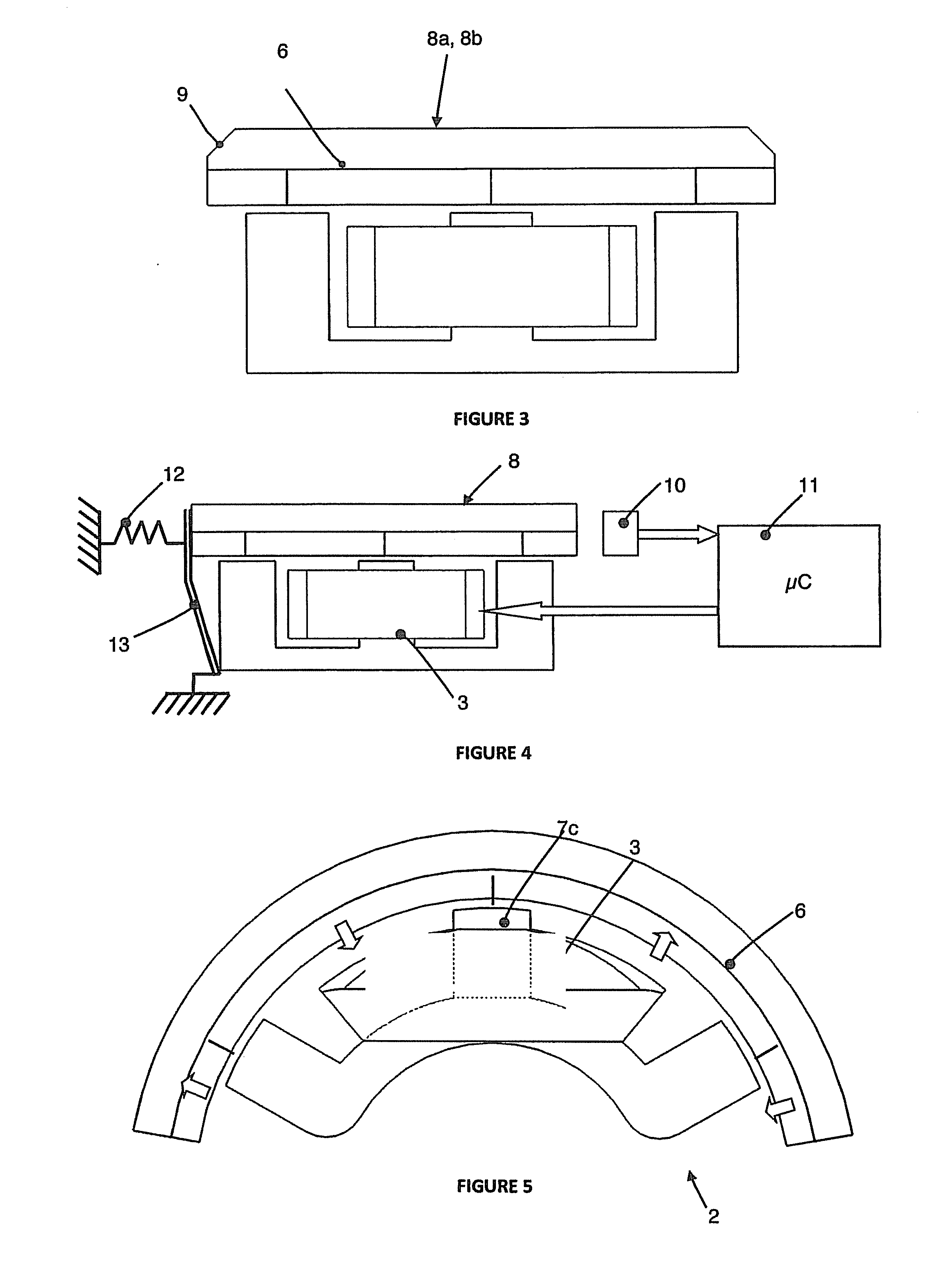
[0032]FIG. 1 shows a front face of an actuator 1 according to the first embodiment of the invention. The actuator comprises a stator unit 2 substantially formed, on the one hand, by a stator 7 made of a mild ferromagnetic material having three poles 7a, 7b and 7c, each extending along the axial direction, oriented vertically in FIG. 1 and contained within the plane of the figure, and, on the other hand, an electric coil 3 surrounding the central pole 7b. The poles 7a, 7b and 7c have all the same width, having the value LP, with such width being measured along a longitudinal direction, oriented horizontally in FIG. 1 and contained within the plane of this figure, i.e. in the direction of the alignment of the poles and perpendicularly to the axial direction.

[0033]The actuator also comprises a magnetic portion 8 positioned parallel to the stator unit 2, facing poles 7a, 7b and 7c, from which it is parted by a mechanical clearance J. Such magnetic portion 8 is selectively moved relative...


PUM


Abstract

An electromagnetic actuator includes a stator unit having N poles having the width LP, and at least one coil surrounding one of the poles, wherein N≦3, and a magnetic portion, which is movable, relative to the stator unit, in a direction of relative movement and over a course of travel C, and including N+1 magnetized areas, the magnetizations of which are perpendicular to the relative movement direction and in alternate directions. The magnetic portion includes a yoke for closing off the magnetic fluxes passing through the magnetized areas, the course of travel C of the magnetic portion being less than or equal to the width LP of each pole, and the thickness of the magnetized areas perpendicular to the direction of movement being less than the course of travel C of the magnetic portion.

Description

CROSS-REFERENCE TO RELATED APPLICATIONS[0001]This application is a National Phase Entry of International Application No. PCT / FR2012 / 050373, filed on Feb. 22, 2012, which claims priority to French patent application Ser. No. 11 / 00541, filed on Feb. 22, 2011, both of which are incorporated by reference herein.TECHNICAL FIELD[0002]Generally speaking, the invention relates to the field of electromagnetic actuators with a limited course of travel, comprising permanent magnets. More particularly, the invention relates to a electromagnetic actuator including at least a stator unit and a magnetic portion, with the stator unit having N poles having the same width LP, and at least one coil surrounding one of said poles, wherein N≧3, and the magnetic portion being movable, relative to the stator unit, in a direction of relative movement and over a course of travel C, and including N+1 magnetized areas, the magnetizations of which are perpendicular to the direction of relative movement and in a...

Claims


Application Information

Patent Timeline
IPC IPC(8): H02K33/18B26B19/38
CPCB26B19/3873H02K33/18H02K33/16B26B19/00H02K7/065H02K35/02
Inventor ARLOT, RICHARDLOUSSERT, GUILLAUME
Owner MOVING MAGNET TECH
Why Eureka
Try Eureka