Charge air cooler component diagnostics

a technology of component diagnostics and air coolers, applied in the direction of combustion air/fuel air treatment, combustion engine, feed system, etc., can solve the problems of turbocharger deformation, overheating of the engine and its associated components, and reducing the cooling capacity of the charge air cooler, so as to increase the density, increase the power, and increase the air temperature

Active Publication Date: 2014-06-05
FORD GLOBAL TECH LLC
View PDF21 Cites 27 Cited by
  • Summary
  • Abstract
  • Description
  • Claims
  • Application Information

AI Technical Summary

Benefits of technology

[0002]Turbocharged and supercharged engines may be configured to compress ambient air entering the engine in order to increase power. Because compression of the air may cause an increase in air temperature, a charge air cooler may be utilized to cool the heated air, thereby increasing its density and further increasing the potential power of the engine. To maintain the charge air cooler at a desired temperature, and to provide a desired level of cooling to the heated air, ambient air may be directed over the charge air cooler via grille shutters positioned at the front of the vehicle. Further, to reduce the accumulation of condensate in the charge air cooler, which may occur when internal surfaces of the charge air cooler are cooler than the dew point of the compressed air, the charge air cooler may include a valve configured to selectively modulate the volume of the charge air cooler, thus increasing the intake flow velocity through the charge air cooler to remove and / or reduce accumulated condensate. If degradation to either the grille shutters or the variable volume valve occurs, the cooling capacity of the charge air cooler may be reduced, leading to overheating of the engine and associated components under some conditions. Further, due to increased air pressure that may result when the variable volume valve is degraded, the turbocharger may degrade.

Problems solved by technology

If degradation to either the grille shutters or the variable volume valve occurs, the cooling capacity of the charge air cooler may be reduced, leading to overheating of the engine and associated components under some conditions.
Further, due to increased air pressure that may result when the variable volume valve is degraded, the turbocharger may degrade.

Method used


Image

  • Charge air cooler component diagnostics
  • Charge air cooler component diagnostics
  • Charge air cooler component diagnostics

Examples


Embodiment Construction

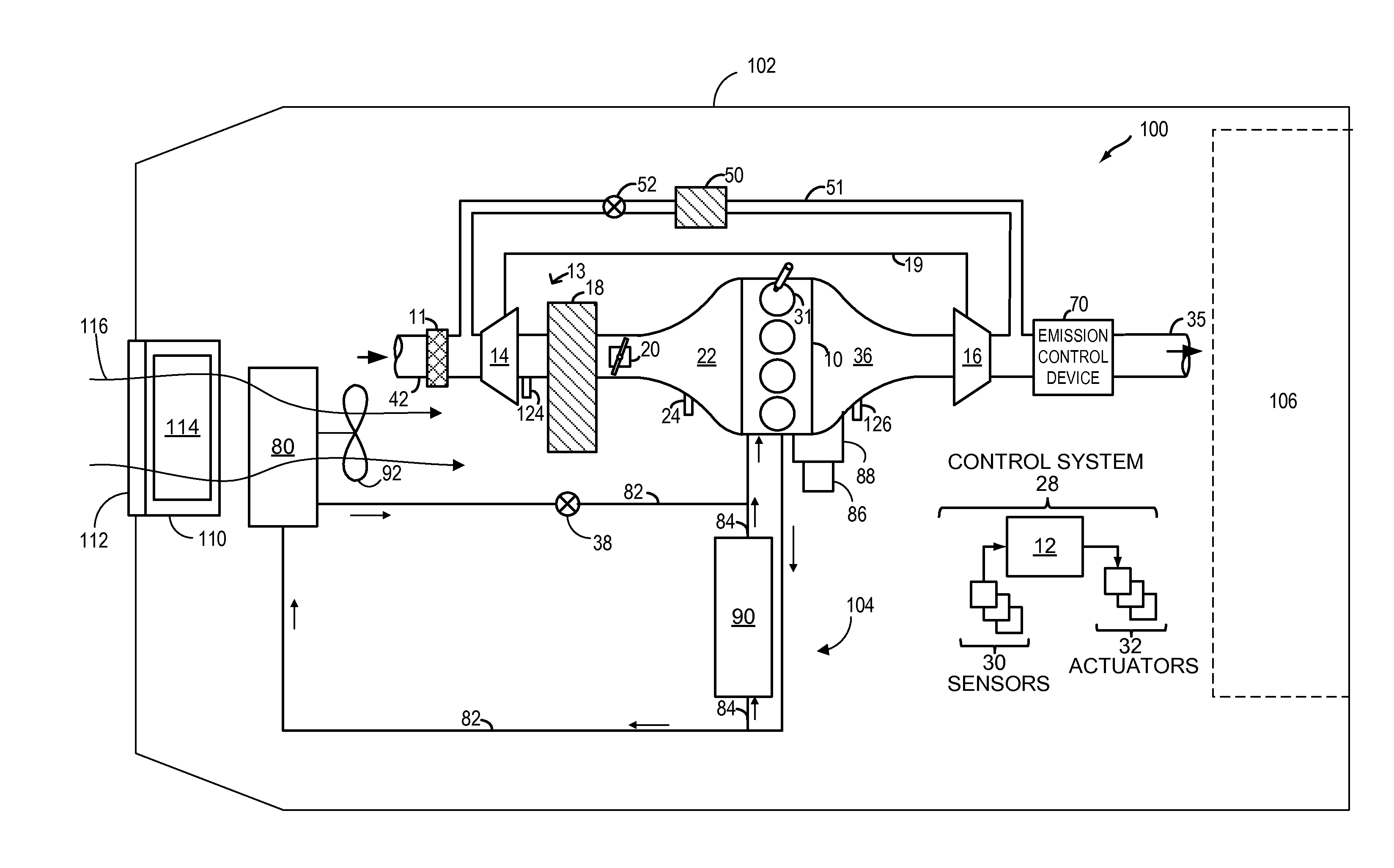
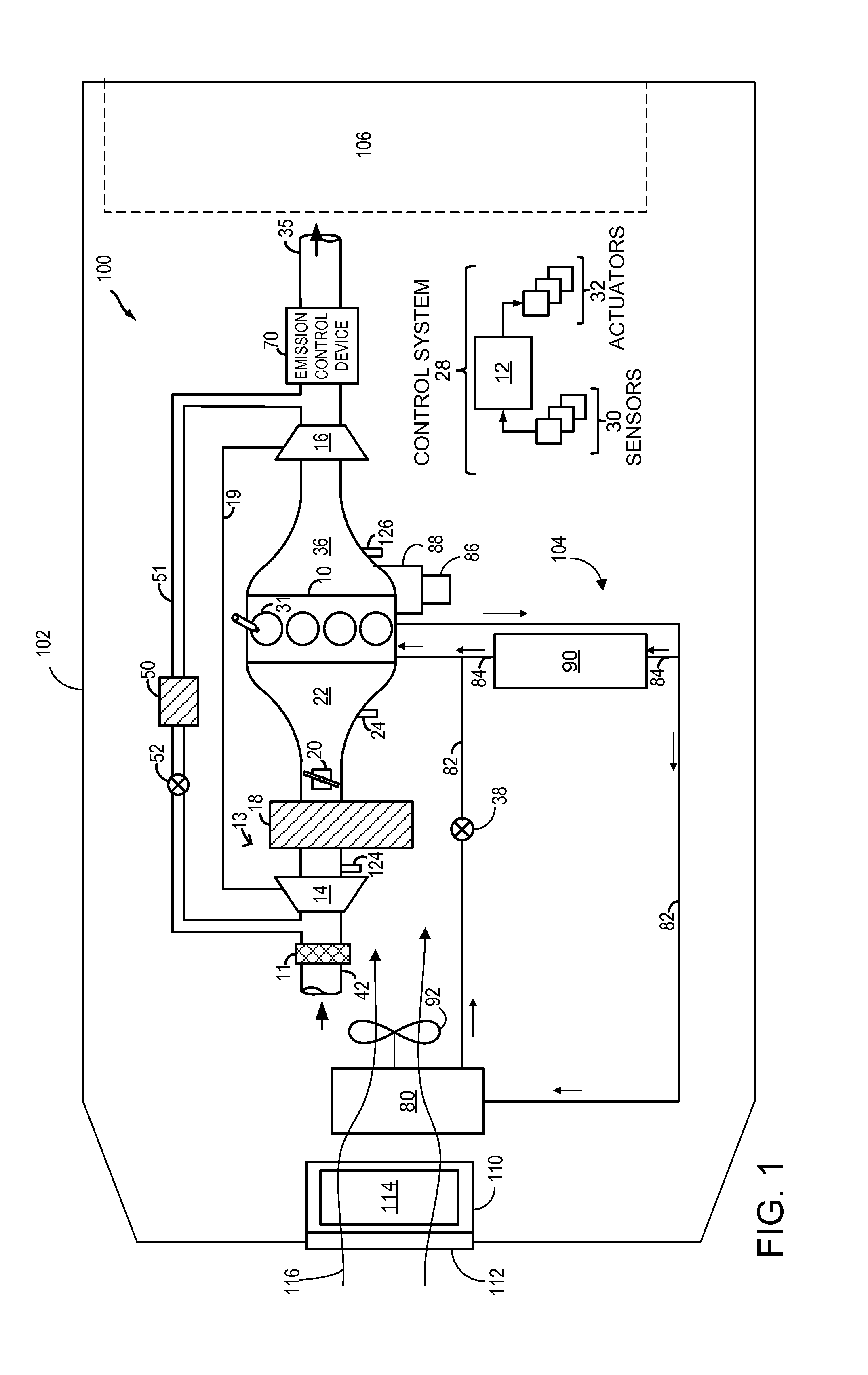
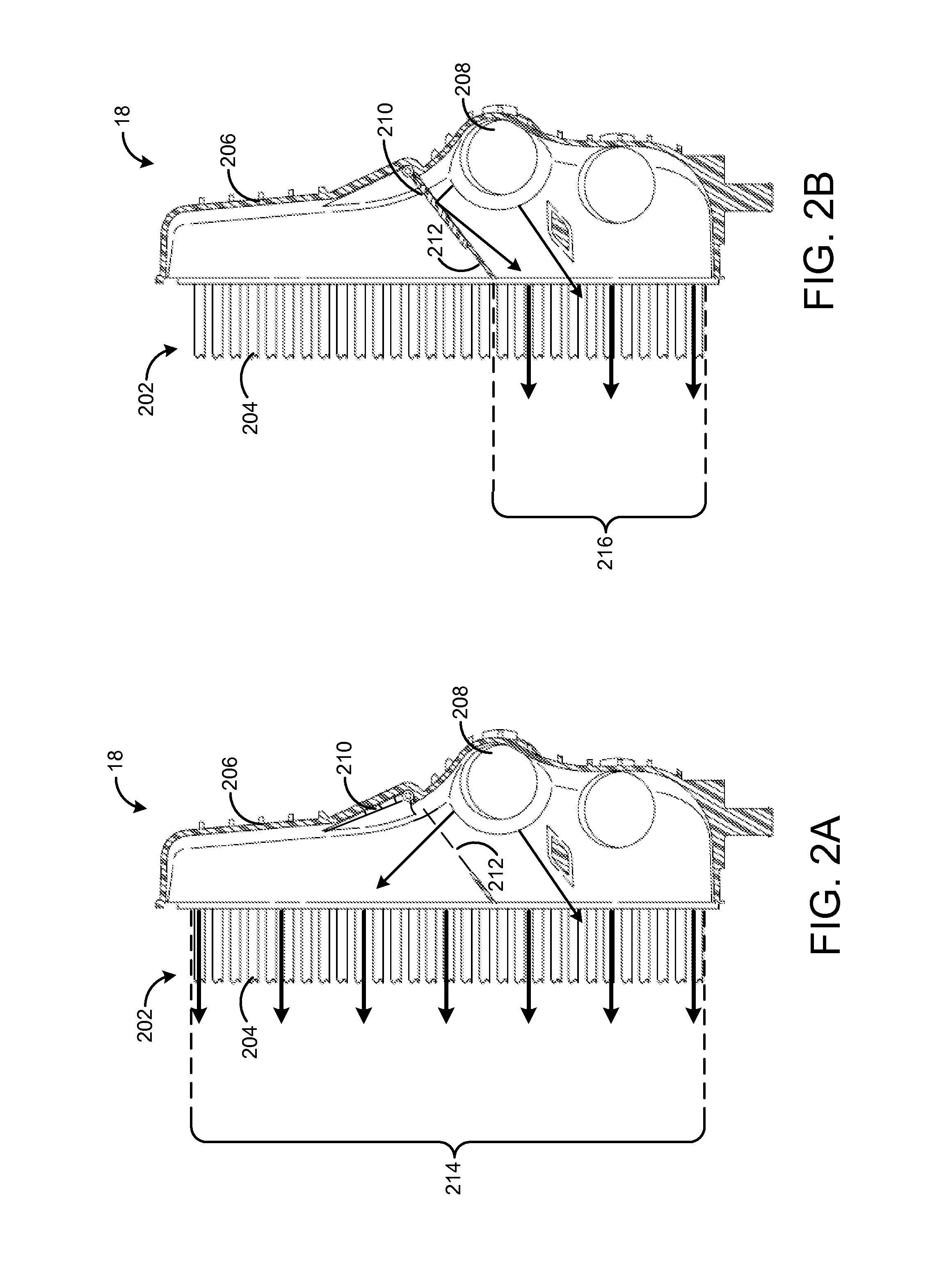
[0012]To diagnose potential degradation of a grille shutter or variable volume charge air cooler valve, an expected temperature or pressure of the charge air cooler may be compared to measured temperature or pressure. If the measured temperature and / or pressure are not equal to the expected temperature and / or pressure, degradation of the grille shutter position or variable volume valve position may be indicated. If the shutters or valve cannot be moved by cycling of the shutter position or valve position, engine operation may be adjusted to reduce potential engine or charge air cooler degradation resulting from the compromised charge air cooling capacity of the charge air cooler. FIG. 1 shows an engine including a charge air cooler, which may have a variable volume valve illustrated in greater detail in FIG. 2, grille shutter system, and controller including instructions to carry out the method illustrated in FIG. 3.

[0013]FIG. 1 shows an example embodiment of a grille shutter system...


PUM


Abstract

Embodiments for a charge air cooler are provided. In one example, a method comprises adjusting an operating parameter in response to a degraded grille shutter, the degraded grille shutter determined based on a temperature difference across a charge air cooler. In this way, degradation of the charge air cooler or engine may be reduced.

Description

FIELD[0001]The present disclosure relates to a charge air cooler for an engine.BACKGROUND AND SUMMARY[0002]Turbocharged and supercharged engines may be configured to compress ambient air entering the engine in order to increase power. Because compression of the air may cause an increase in air temperature, a charge air cooler may be utilized to cool the heated air, thereby increasing its density and further increasing the potential power of the engine. To maintain the charge air cooler at a desired temperature, and to provide a desired level of cooling to the heated air, ambient air may be directed over the charge air cooler via grille shutters positioned at the front of the vehicle. Further, to reduce the accumulation of condensate in the charge air cooler, which may occur when internal surfaces of the charge air cooler are cooler than the dew point of the compressed air, the charge air cooler may include a valve configured to selectively modulate the volume of the charge air coole...

Claims


Application Information

Patent Timeline
Patent Type & Authority Applications(United States)
IPC IPC(8): F02M31/20
CPCF02M31/205F02M35/1038F02B29/0418F02B29/0431F02B29/0437F02B29/0493F02M26/06F02M26/23Y02T10/12
Inventor SMITH, CRAIG ALANWHITEHEAD, JOSEPH PATRICKGLUGLA, CHRIS PAULCOCKERILL, CHARLES ALLEN
Owner FORD GLOBAL TECH LLC
Why Eureka
Try Eureka