Plants for advanced treatment of wastewater and method for treating wastewater using thereof

a technology for wastewater treatment and advanced treatment, applied in biological water/sewage treatment, multi-stage water/sewage treatment, membranes, etc., can solve the problems of high maintenance and administration fees for cleaning and replacing membranes, difficult operation of efficient methods, and high power operation costs, so as to reduce the degree of contamination and reduce the energy consumption of the process , the effect of easy control of membrane contamination

Inactive Publication Date: 2014-06-05
KOREA INST OF SCI & TECH
View PDF9 Cites 22 Cited by
  • Summary
  • Abstract
  • Description
  • Claims
  • Application Information

AI Technical Summary

Benefits of technology

[0012]The invention has been made in an effort to solve problems of the conventional activated sludge treatment process and advanced wastewater treatment process, and is directed to provide an advanced wastewater treatment apparatus being able to minimize energy consumption at a separation of feed water and purified water and to minimize membrane pollution phenomenon generated by the feed water.
[0013]The invention is directed to increase efficiency of an anaerobic digester and a collect rate of bio gas in an aspect reuse of wastewater energy.
[0020]According to the exemplary embodiment of the invention, it is no need to apply pressure to the separation membrane because the advanced wastewater treatment apparatus using the membrane separation process of forward osmosis uses the naturally-generated osmotic pressure, contrary to the conventional advanced wastewater treatment apparatus using the membrane separation process. Thus, the energy consumption during the process can be largely reduced. Also, a degree of contamination generated by a flow of feed water is low, and thus, the tangle of the separation membrane is not induced. Accordingly, the control of the membrane contamination is easy. Also, unlike the conventional advanced wastewater treatment apparatus using the membrane separation process, an artificial pressure is not applied in the invention. Thus, loads being applied to the membrane and a membrane module used during the process are very small. Accordingly, the damage of the membrane and the module can be largely reduced. In addition, a kind and concentration of the draw solution can be selectively used, and thus, purified water can be separated even from high-concentrated sludge.
[0021]Also, in the advanced wastewater treatment apparatus according to the invention, the ammonia amount of the sludge supplied to the anaerobic digester can be minimized by the ammonia removal device. Accordingly, the activation of anaerobes that are vulnerable to the ammonia can be maximized, and thus, digestive efficiency of the anaerobic digester can be maximized. Particularly, in the invention, since the ammonia of the concentrated sludge can be minimized, the digestive efficiency of the anaerobic digester can be enhanced. Thus, the collect rate or the recovery factor of the bio gas such as methane (CH4) can increase.

Problems solved by technology

Recently, in an advanced wastewater treatment of activated sludge operated in South Korea, an efficient operation of the method may be difficult and small-to-middle sized facilities may generally used because seasonal water quality variations are large and carbon / nitrogen ratio, which is a ratio of an organic material necessary to eliminate nitrogen and phosphorus, is low.
In the cross-flow MBR process, a system is very complicate and uses high pressure, and thus, power operation cost is very high.
Also, because the system uses the high pressure, a surface of the membrane may be heavily polluted, and maintenance and administration fee for cleaning and a replacing the membrane, and so on may increase.
In the submerged MBR process, it is difficult to control the sludge of high concentration, and a tangle of the membrane may be induced by concomitants or contaminants such as hair.
Also, in the process of a hollow-fiber type, the separation membrane and module may be damaged.
However, when the seasonal water quality variations are large and inflow concentration is low, efficiency is low according to the conventional process.
Also, in the anaerobic digestion process, yield of the bio gas is low because the growth of anaerobes is limited due to high nitrogen concentration.

Method used


Image

  • Plants for advanced treatment of wastewater and method for treating wastewater using thereof
  • Plants for advanced treatment of wastewater and method for treating wastewater using thereof

Examples


Embodiment Construction

[0023]Hereinafter, an embodiment of the invention will be described in more detail.

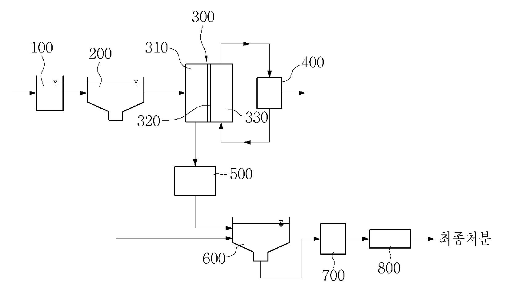
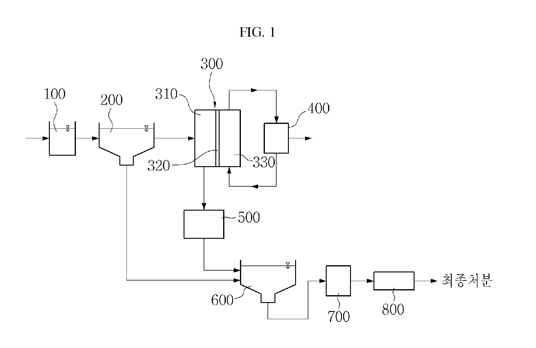
[0024]The invention relates to an advanced wastewater treatment apparatus, and more particularly, to an advanced wastewater treatment apparatus including a forward osmosis module, a draw-solution separation device, and an ammonia removal device. The forward osmosis module is installed after a first settling tank. The first settling tank performs a first sedimentation process of inflow water. In this instance, the inflow water flows into the first settling tank after passing through a grit chamber. The forward osmosis module includes an inflow-water side where first-treated water treated by the first settling tank flows from the first settling tank, a separation membrane for allowing water of the first-treated water to pass therethrough by forward osmosis induced by osmotic pressure difference, and a draw-solution side where the draw solution flows for inducing the osmotic pressure difference between t...


PUM

PropertyMeasurementUnit
osmotic pressureaaaaaaaaaa
energyaaaaaaaaaa
sizeaaaaaaaaaa

Abstract

The invention relates to an advanced wastewater treatment apparatus that may include a forward osmosis module, a draw-solution separation device, and an ammonia removal device. The forward osmosis module may be installed after a first settling tank, and may include an inflow-water side where water treated by the first settling tank flows, a separation membrane for allowing the treated water to pass therethrough, and a draw-solution side where the draw solution flows. The draw-solution separation device may separate the draw solution and the water of the draw solution, return the separated draw solution to the draw-solution side of the forward osmosis module, and discharge the separated water to the outside. The ammonia removal device may eliminate the ammonia from the treated water of the forward osmosis module.

Description

CROSS-REFERENCE TO RELATED APPLICATION[0001]This application claims priority to and the benefit of Korean Patent Application No. 10-2012-0137499 filed in the Korean Intellectual Property Office on Nov. 30, 2012, the entire contents of which are incorporated herein by reference.BACKGROUND OF THE INVENTION[0002](a) Field of the Invention[0003]The invention relates to an advanced treatment apparatus for treating wastewater with low energy.[0004](b) Description of the Related Art[0005]Recently, in an advanced wastewater treatment of activated sludge operated in South Korea, an efficient operation of the method may be difficult and small-to-middle sized facilities may generally used because seasonal water quality variations are large and carbon / nitrogen ratio, which is a ratio of an organic material necessary to eliminate nitrogen and phosphorus, is low. Particularly, when a technique developed in a foreign country is applied in our country, technical reviews or overviews (such as changi...

Claims


Application Information

Patent Timeline
Patent Type & Authority Applications(United States)
IPC IPC(8): C02F9/00
CPCC02F9/00C02F1/28C02F1/445C02F3/28C02F2101/16B01D61/58B01D61/002B01D61/025B01D2311/2688B01D2311/08Y02E50/30C02F1/44B01D61/0022B01D61/0021
Inventor HEON, LEE SEOCKHUN, NA YONGHEUN, YANG SEUNG
Owner KOREA INST OF SCI & TECH
Why Eureka
Try Eureka