Supercharge Your Innovation With Domain-Expert AI Agents!

High compliance laser driver circuit

a laser diode and driver circuit technology, applied in the direction of laser details, semiconductor lasers, electrical apparatus, etc., can solve the problems of data pattern dependency, low output data value, and non-stable or constant voltage vsub>rmod /sub>across the resistor rsub>mod /sub>,

Active Publication Date: 2014-06-05
MICREL
View PDF2 Cites 1 Cited by
  • Summary
  • Abstract
  • Description
  • Claims
  • Application Information

AI Technical Summary

Benefits of technology

The invention relates to a laser driver circuit for a laser diode that improves the noise level of the laser diode. The invention includes a feedback control for regulating the laser diode modulation current, which compensates for variations in output power levels due to factors such as laser aging and temperature variations. The invention also includes a data-independent feedback control loop that ensures a constant modulation current value regardless of the input data pattern. The invention provides a more stable and constant modulation current, which is particularly useful for low output data values.

Problems solved by technology

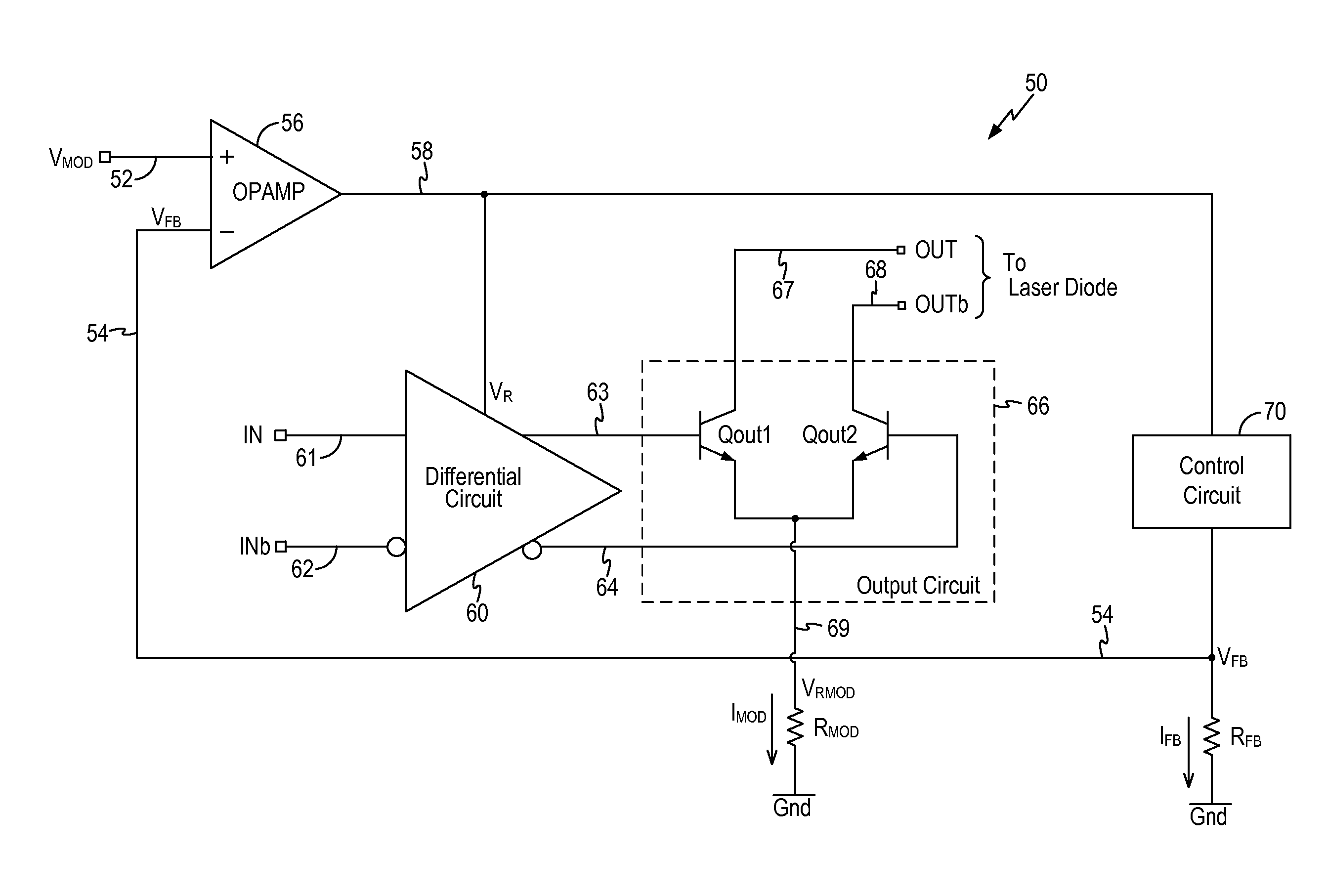
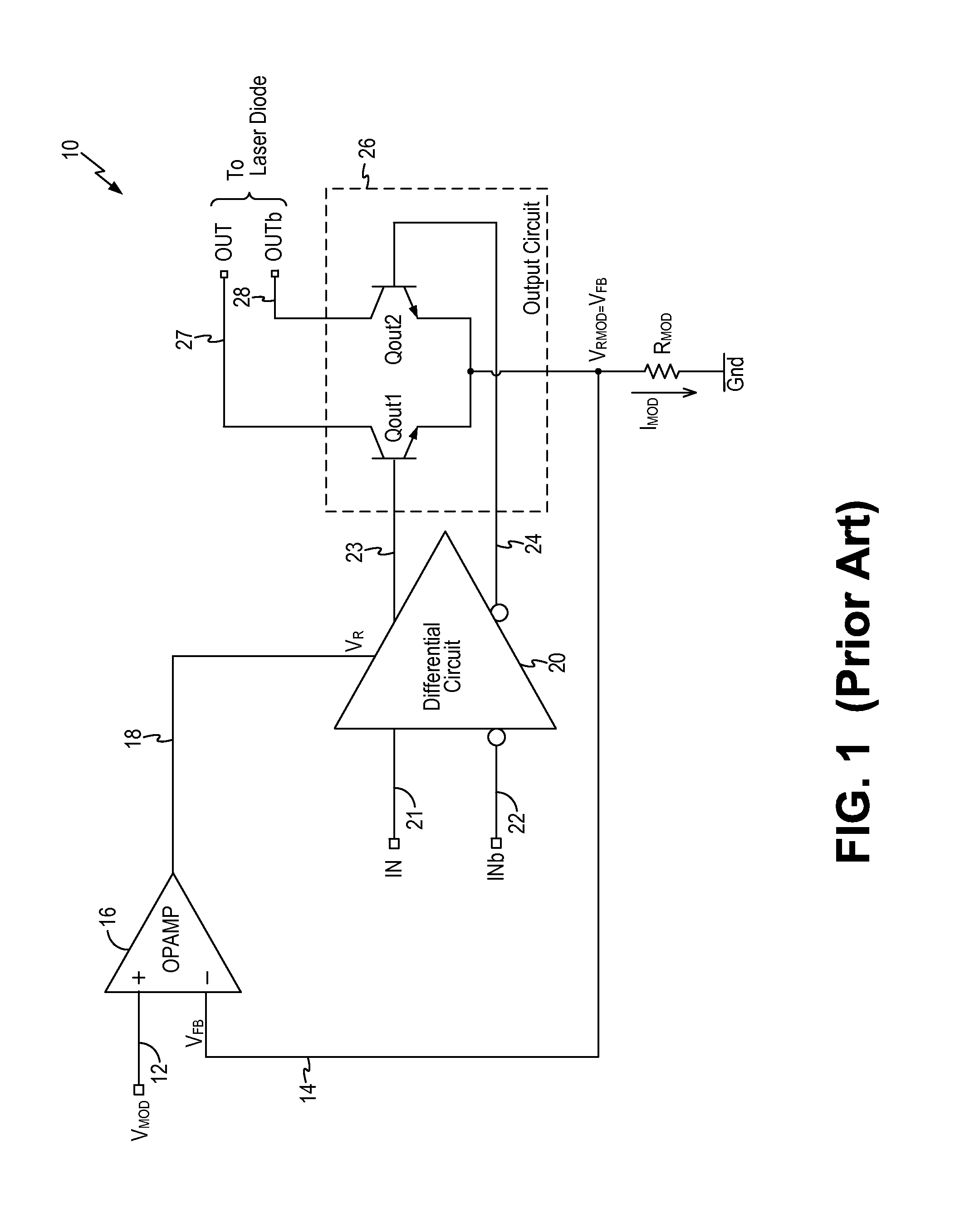
However, because resistor RMOD is connected to the emitter terminals of transistors Qout1 and Qout2 which are moving in accordance with the input data pattern, the voltage VRMOD across the resistor RMOD is not a stable or constant value.
The data pattern dependency is particularly problematic for low output data values.

Method used


Image

  • High compliance laser driver circuit
  • High compliance laser driver circuit
  • High compliance laser driver circuit

Examples


Embodiment Construction

[0012]The invention can be implemented in numerous ways, including as a process; an apparatus; a system; and / or a composition of matter. In this specification, these implementations, or any other form that the invention may take, may be referred to as techniques. In general, the order of the steps of disclosed processes may be altered within the scope of the invention.

[0013]A detailed description of one or more embodiments of the invention is provided below along with accompanying figures that illustrate the principles of the invention. The invention is described in connection with such embodiments, but the invention is not limited to any embodiment. The scope of the invention is limited only by the claims and the invention encompasses numerous alternatives, modifications and equivalents. Numerous specific details are set forth in the following description in order to provide a thorough understanding of the invention. These details are provided for the purpose of example and the inv...


PUM


Abstract

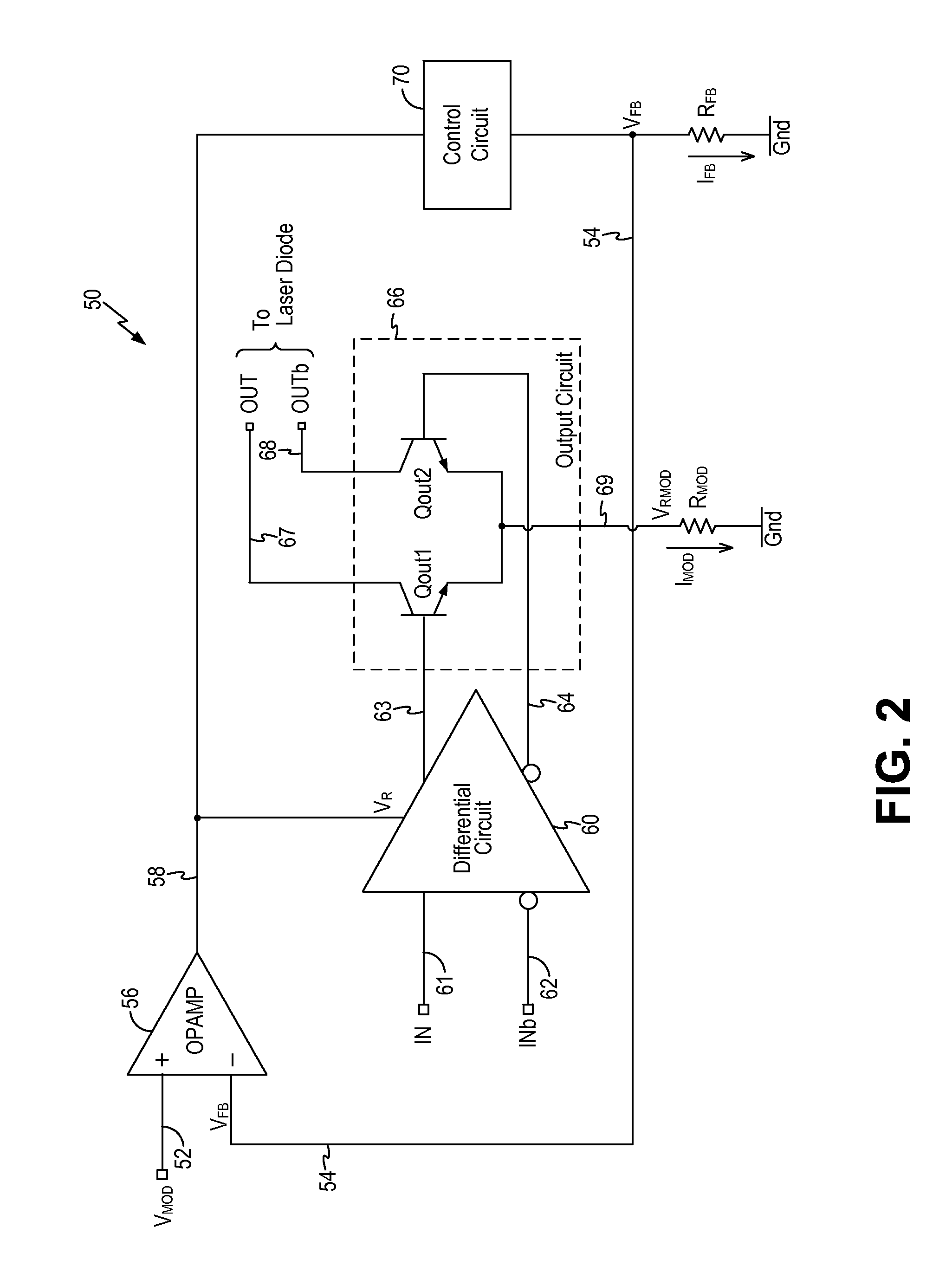
A laser driver circuit having a differential circuit and an output circuit includes a control circuit receiving a regulated supply voltage that also supplies the differential circuit as an input signal. The control circuit generates a feedback voltage across a first resistor to cause a first current to flow in the first resistor having a current value equal or proportional to the modulation current value. The laser driver circuit includes an operational amplifier receiving the feedback voltage and a reference voltage indicative of a desired modulation current value and to generate the regulated supply voltage. The control circuit and the operational amplifier form a feedback control loop to adjust the regulated supply voltage to regulate the feedback voltage to be equal to the reference voltage, thereby regulating the modulation current value to the desired modulation current value.

Description

BACKGROUND OF THE INVENTION[0001]The invention relates to a driver circuit for a laser diode and, in particular, to a laser driver circuit for a laser diode with improved noise level.[0002]Optical communication systems commonly employ semiconductor lasers or other optical emitters for transmitting light signals indicative of a low data value and a high data value, as represented by different light intensity levels. Semiconductor lasers, such as edge emitting lasers (Distributed Feedback (DFB) lasers and Fabry-Perot lasers) and vertical cavity surface emitting lasers (VCSEL), are well known. Semiconductor lasers or optical emitters may be used to form a fiber optics transmitter or an optical transceiver.[0003]A semiconductor laser, also called a laser diode, requires a bias current above a threshold level applied to the laser to turn the laser on so that lasing can occur. Once the laser is turned on, that is, the bias current is above the threshold level, the laser can transmit data ...

Claims


Application Information

Patent Timeline
IPC IPC(8): H01S3/10
CPCH01S3/10H01S5/0427H01S5/06808
Inventor NEUMANN, BERNDKUEHNEL, DIETERPOHLAND, MAIK
Owner MICREL
Features
  • R&D
  • Intellectual Property
  • Life Sciences
  • Materials
  • Tech Scout
  • Unparalleled Data Quality
  • Higher Quality Content
  • 60% Fewer Hallucinations
Learn More