
Bioreactor using acoustic standing waves

a bioreactor and standing wave technology, applied in the field of biotechnology, can solve the problems of high start-up cost of fed-batch bioreactor, high cost of bioreactor, and high complexity of cell retention system in the perfusion process

Active Publication Date: 2014-06-05
FLODESIGN SONICS
View PDF7 Cites 46 Cited by
  • Summary
  • Abstract
  • Description
  • Claims
  • Application Information

AI Technical Summary

Benefits of technology

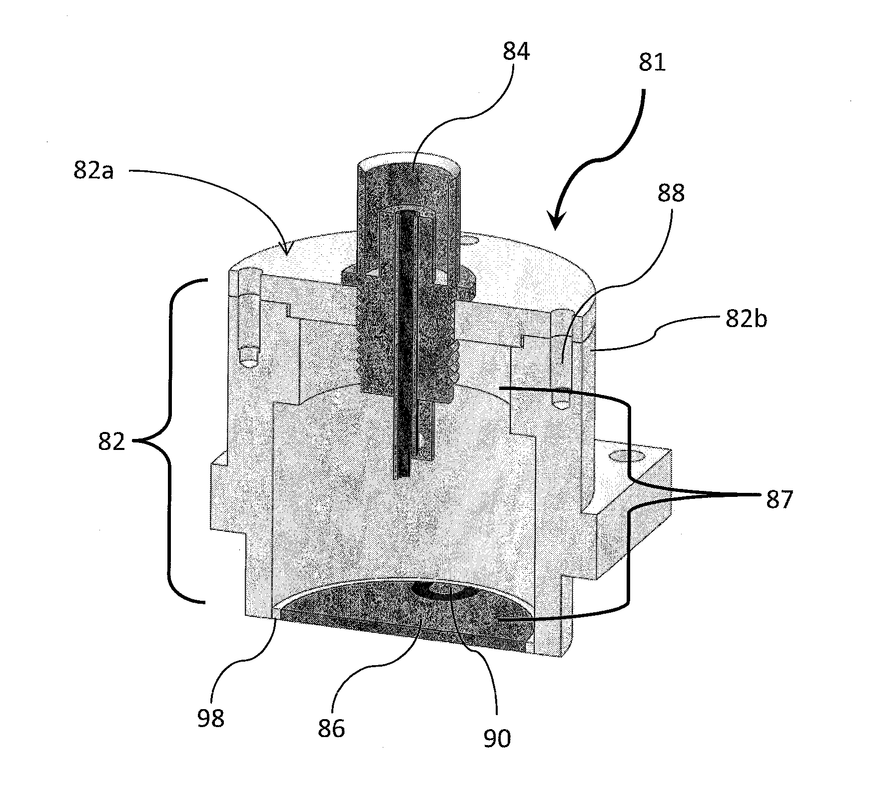
The present disclosure relates to a system for producing biomolecules, such as recombinant proteins or monoclonal antibodies, and separating them from a cell culture in a bioreactor. The system includes a filtering device with an ultrasonic transducer and a reflector that creates a multi-dimensional standing wave in the flow chamber. The filtering device can recover the desired product and recycle the fluid back to the bioreactor. The use of the multi-dimensional standing wave creates an axial force and a lateral force in the flow chamber, improving the separation process. The system can also operate as a perfusion bioreactor. The ultrasonic transducer is made of piezoelectric material and can vibrate in a higher order mode shape. The filtering device can be disposable and includes a jacket for regulating the fluid temperature. The system is efficient and effective in separating biomolecules and producing them in high purity.

Problems solved by technology

However, a fed-batch bioreactor has high start-up costs, and generally has a large volume to obtain a cost-effective amount of product at the end of the growth cycle.
After the batch is completed, the bioreactor must be cleaned and sterilized, resulting in nonproductive downtime.
These cell retention systems add a level of complexity to the perfusion process, requiring management, control, and maintenance for successful operation.
Operational issues such as malfunction or failure of the cell retention equipment has previously been a problem with perfusion bioreactors.
This has limited their attractiveness in the past.

Method used


Image

  • Bioreactor using acoustic standing waves
  • Bioreactor using acoustic standing waves
  • Bioreactor using acoustic standing waves

Examples


first embodiment

[0068]FIG. 4 is an acoustophoretic filtering device 400. The device includes a flow chamber 410, which is depicted here as a cylindrical pipe or tube. A feed inlet 412 is illustrated here at the bottom of the flow chamber, through which fluid from the bioreactor is received. An outlet 414 is depicted at the top of the flow chamber, with the arrows (reference numeral 415) indicating the direction of fluid flow. A sleeve 420 surrounds the flow chamber. The sleeve includes at least one ultrasonic transducer 422 and at least one reflector 424, which are located opposite each other. Together, the transducer and reflector generate one or more standing waves 425, with the reflector bouncing the initial propagated wave back towards the transducer with a similar frequency and intensity to form an acoustic standing wave. It is particularly contemplated that the sleeve can be separated from the flow chamber / pipe. The pipe can be discarded and replaced with a new pipe. This allows for disposabl...

second embodiment

[0069]FIG. 5 is the acoustophoretic filtering device. Here, the filtering device 400 also includes a jacket 430 that is located between the sleeve 420 and the flow chamber 410. The jacket contains a temperature-regulating fluid 432 that can be used to control the temperature of the fluid passing through the flow chamber. In this regard, it is usually desirable to maintain the temperature of the cell culture below 38° C. to prevent compromise of the cells. The temperature-regulating fluid is completely separated from the cell culture media / fluid passing through the flow chamber 410. It is noted that the standing wave 425 created by the transducer 422 and reflector 424 will propagate through the jacket 430 and the temperature regulating fluid 432 therein, and will continue to operate in the flow chamber to separate the targeted material in the flow chamber.

[0070]FIG. 6 illustrates an exemplary processing system of the present disclosure, comprising a bioreactor 610 and a filtering dev...


PUM

PropertyMeasurementUnit
Thicknessaaaaaaaaaa
Temperatureaaaaaaaaaa
Thicknessaaaaaaaaaa

Abstract

A perfusion bioreactor includes at least one ultrasonic transducer that can acoustically generate a multi-dimensional standing wave. The standing wave can be used to retain cells in the bioreactor, and can also be utilized to dewater or further harvest product from the waste materials produced in a bioreactor.

Description

CROSS-REFERENCE TO RELATED APPLICATIONS[0001]This application claims priority to U.S. Provisional Patent Application Ser. No. 61 / 761,717, filed on Feb. 7, 2013. This application is also a continuation-in-part of U.S. patent application Ser. No. 14 / 026,413, filed on Sep. 13, 2013, which claims the benefit of U.S. Provisional Patent Application Ser. No. 61 / 708,641, filed on Oct. 2, 2012, and is also a continuation-in-part of U.S. Ser. No. 13 / 844,754, filed Mar. 15, 2013, which claimed the benefit of U.S. Provisional Patent Application Ser. No. 61 / 611,159, filed Mar. 15, 2012, and of U.S. Provisional Patent Application Ser. No. 61 / 611,240, also filed Mar. 15, 2012, and of U.S. Provisional Patent Application Ser. No. 61 / 754,792, filed Jan. 21, 2013. These applications are incorporated herein by reference in their entireties.BACKGROUND[0002]The field of biotechnology has grown tremendously in the last 20 years. This growth has been due to many factors, some of which include the improveme...

Claims


Application Information

Patent Timeline
IPC IPC(8): C12M1/12
CPCC12M25/00B06B1/0644B01D17/04B01D17/06B01D21/283C12M29/10C12M33/08C12M35/04C12M47/02H10N30/2047
Inventor LIPKENS, BARTMASI, LOUISKOWALSKI, III, STANLEYPRESZ, JR., WALTER M.DIONNE, JASONDUTRA, BRIANMERCADO, ARIKENNEDY, III, THOMAS J.MARTIN, ARTHUR
Owner FLODESIGN SONICS
Learn More