Method of examining tissue growth and conditioning of cells on a scaffold and a perfusion bioreactor

a perfusion bioreactor and tissue growth technology, applied in biomass after-treatment, biochemical apparatus and processes, specific use bioreactors/fermenters, etc., can solve the problems of affecting the life of patients, thrombosis, injury or surgery, and the risk of significant risk or danger for patients, so as to improve the efficiency of heat exchange and facilitate the integration and assembly. , the effect of easy assembly

Inactive Publication Date: 2013-12-26
LUDWIG MAXIMILIANS UNIV MUNCHEN
View PDF1 Cites 7 Cited by
  • Summary
  • Abstract
  • Description
  • Claims
  • Application Information

AI Technical Summary

Benefits of technology

[0026]Further, the heat exchange means preferably comprise inlet and outlet ports for feeding and discharging a heating fluid to and from said bioreactor, respectively. Herein, the heating fluid inlet port is preferably located closer to the nutrition solution outlet port, and the heating fluid outlet port is located closer to the nutrition solution inlet port. This way, the flow directions of the nutrition solution and the heating fluid are generally opposite to each other, hence allowing for an increased efficiency of the heat exchange.
[0027]Note that with such ports, the perfusion bioreactor can be easily combined with external supplies for nutrition solution and heating fluid, respectively. Accordingly, the experimental setup can be easily assembled, and the bioreactor can be quickly exchanged, thereby allowing scientists to carry out different experiments with different cells and scaffolds quickly one after another by simply exchanging the perfusion bioreactors. In fact, as will be shown below with regard to a specific embodiment, the perfusion bioreactor of the invention can be manufactured at very reasonable costs so that in practice it may be provided as a disposable article. By providing the ports at the perfusion bioreactor, such one-way product can be easily combined with stationary equipment for providing the nutrition solution and / or the heating fluid.
[0028]In a preferred embodiment, the housing of the perfusion bioreactor comprises a cavity for receiving said heating fluid, and at least a part of said first and / or second channel(s) is (are) disposed in said cavity such as to be at least partially surrounded by said heating fluid. This way, the temperature of the nutrition solution can be easily and efficiently adjusted upon flow through the first and / or second channels within the bioreactor.
[0029]Preferably, the heating fluid receiving cavity is partitioned into at least two compartments by at least one partitioning wall, wherein said partitioning wall has at least one opening allowing a flow of heating fluid from one compartment to another. By providing separate compartments with restricted flow from one compartment to another, a more uniform temperature distribution in the heating fluid inside the bioreactor is achieved.
[0030]Preferably, the first and / or second nutrition solution channel(s) is (are) formed by a bore in said partitioning wall. This is a very cost-efficient way of providing the channel within the bioreactor and at the same time ensures an efficient heat exchange between the heating fluid and the nutrition solution guided in said first and / or second channel(s).

Problems solved by technology

While mechanical artificial heart valves have good lifetimes, unfortunately, they bear a severe risk of thrombosis, meaning that patients with artificial mechanical heart valves have to use anticoagulation medication throughout their lives.
This is highly undesirable, because due to the decreased coagulation, any injury or surgery involves a significant risk or danger for the patient.
While biological heart valves and homografts have good haemodynamic properties, unfortunately their lifetime is rather limited.
In addition, there is a risk that the patient's body does not accept the biological homograft implant or that an inflammatoric reaction may occur.
It has been shown that with this three layer construction, the attachment of the endothelium cells has been improved as compared to a simple construction, but the attachment is unfortunately generally not strong enough to withstand shear forces that will occur during operation (see Fang Ning-tao, Xie Shang-zhe, Construction of tissue-engineered heart valves by using decellularized scaffolds and endothelial progenitor cells, Chin Med. 120, 2007, Vol. 8, pp.
For example, it may very well be that certain cells grow well on certain scaffolds under statical conditions, but will not withstand the physiological flow occurring when the tissue is employed in the vascular system.
Unfortunately, determining the best combinations of scaffold, cells and tissue growth conditions is a very time consuming task.
This means that it may well take one month to grow a tissue that then turns out to be entirely useless.

Method used


Image

  • Method of examining tissue growth and conditioning of cells on a scaffold and a perfusion bioreactor
  • Method of examining tissue growth and conditioning of cells on a scaffold and a perfusion bioreactor
  • Method of examining tissue growth and conditioning of cells on a scaffold and a perfusion bioreactor

Examples


Embodiment Construction

[0041]For the purposes of promoting an understanding of the principles of the invention, reference will now be made to the preferred embodiment illustrated in the drawings, and specific language will be used to describe the same. It will nevertheless be understood that no limitation of the scope of the invention is thereby intended, such alterations and further modifications in the illustrated device and method and such further applications of the principles of the invention as illustrated therein being contemplated therein as would normally occur now or in the future to one skilled in the art to which the invention relates.

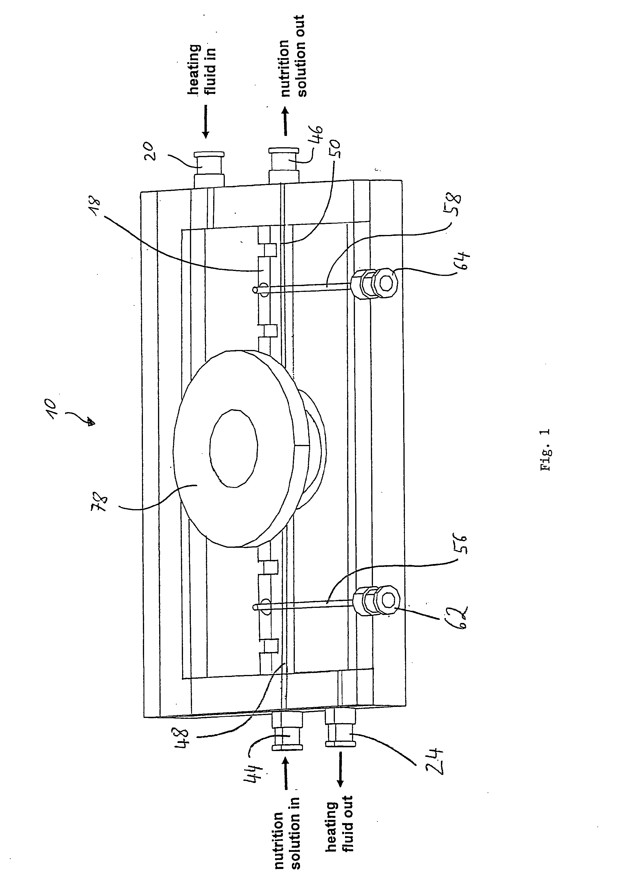
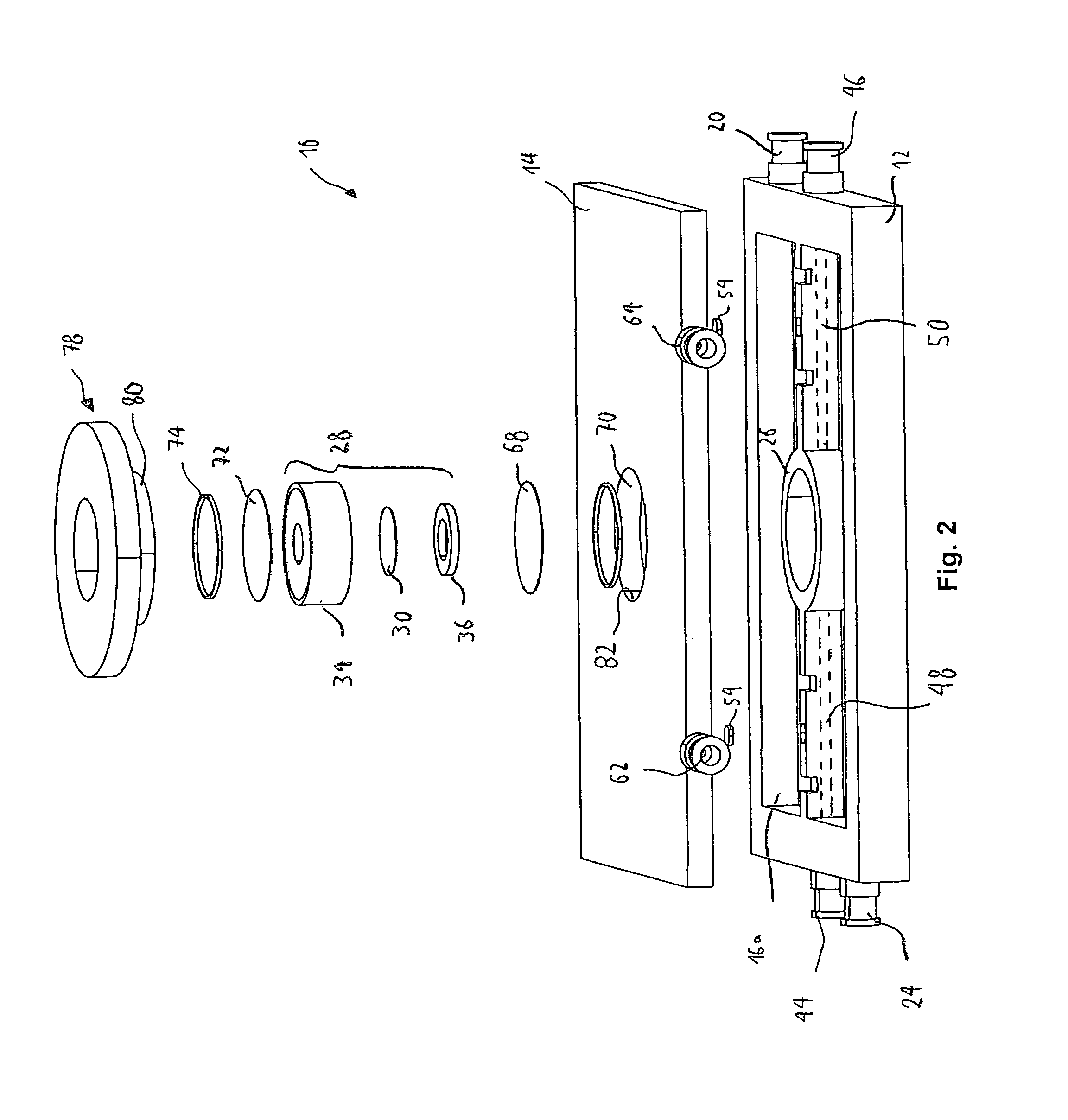
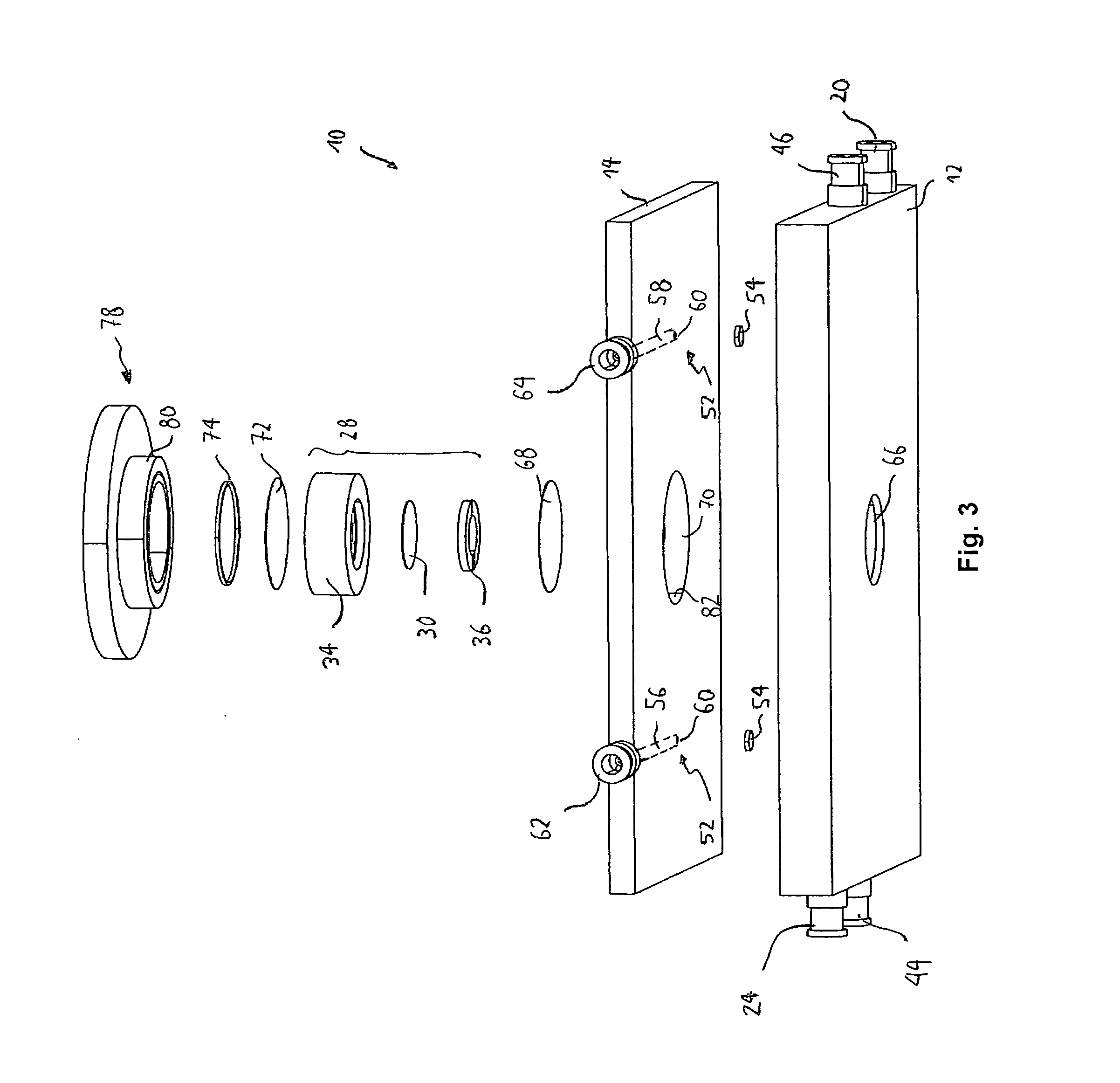
[0042]FIG. 1 shows a perspective and partially transparent view of a bioreactor 10 in the assembled state according to an embodiment of the invention. The same bioreactor 10 is also shown in FIG. 2 which is a perspective, exploded view of the bioreactor 10 as seen from an upper angle, and in FIG. 3, which is the same exploded view as FIG. 2 but seen from a lower ...


PUM

PropertyMeasurementUnit
flow speedaaaaaaaaaa
areaaaaaaaaaaa

Abstract

Disclosed herein is a method of examining tissue growth and/or conditioning and/or adhesion properties of cells on a synthetic and/or natural scaffold (30) as well as a perfusion bioreactor (10) for use in this method. The method comprises the following steps: fixing a scaffold (30) to a holding means (28) disposed or disposable in a perfusion bioreactor (10), generating a flow of nutrition solution along the surface of said scaffold (30) held by said holding means (28), generating and/or maintaining physiological conditions in said nutrition solution flowing along said scaffold (30) using heat exchange means (20, 24, 48, 50) and/or gas exchange means (52, 54, 56, 58, 60, 62, 64) associated with said bioreactor (10), such as to allow growth and/or conditioning of cells on said scaffold (30), and optically inspecting, in particular by microscopy, the scaffold (30) held by said holding means (28) through a window (66, 68, 70, 72) provided in said perfusion bioreactor (10) at different times or continuously during tissue growth and/or conditioning of cells on said scaffold (30) while maintaining said physiological conditions in said perfusion bioreactor (10).

Description

FIELD OF THE INVENTION[0001]The present invention relates to the field of tissue engineering. In particular, the invention relates to a method of examining tissue growth and / or conditioning and / or adhesion properties of cells on a scaffold, and a perfusion bioreactor to be employed in such method. Herein, the scaffold may be either one of a synthetic or a natural scaffold.RELATED PRIOR ART[0002]Worldwide, every year approximately 300,000 heart valves are implanted to patients. Currently, there are three different types of implants available, namely mechanical heart valves, biological heart valves and homografts. While mechanical artificial heart valves have good lifetimes, unfortunately, they bear a severe risk of thrombosis, meaning that patients with artificial mechanical heart valves have to use anticoagulation medication throughout their lives. This is highly undesirable, because due to the decreased coagulation, any injury or surgery involves a significant risk or danger for th...

Claims


Application Information

Patent Timeline
Patent Type & Authority Applications(United States)
IPC IPC(8): C12M1/34
CPCC12M41/46C12M29/10C12M35/04C12M41/18C12M21/08
Inventor AKRA, BASSILHAAS, ULRIKEHOLLWECK, TRIXI
Owner LUDWIG MAXIMILIANS UNIV MUNCHEN
Why Eureka
Try Eureka