Intervertebral dynamic fixation implant

a dynamic fixation and intervertebral technology, applied in the field of spine implants, can solve the problems of severe disability, pain, overload at the junction, and discomfort of subjects suffering from these disorders, and achieve the effects of increasing the mobility of the spine, good vertebral anchorage, and effective and lasting stabilization

Inactive Publication Date: 2014-06-05
DUBOIS GILLES +1
View PDF1 Cites 8 Cited by
  • Summary
  • Abstract
  • Description
  • Claims
  • Application Information

AI Technical Summary

Benefits of technology

[0012]To overcome the drawbacks of the prior art, the present invention proposes a new implant for dynamic fixation of vertebral bodies, without bone fusion, providing good vertebral anchorage, so as to ensure an effective and lasting stabilization over time of one or more functional units while allowing increased mobility of the spine.
[0013]One objective of the spinal implant of the invention is to limit the traumatic shock related to surgery, in particular by reducing the number of pedicle screws used during the surgery.
[0014]Another objective of the spinal implant of the present invention is to provide a robust and intimate fixation system for attachment to the vertebral bodies, easily readjustable to the anatomy of the patient during the operation.

Problems solved by technology

These functions can be altered by natural wear, pathological degeneration, or traumatic shock, resulting in discomfort, pain, or even severe disability in subjects suffering from these disorders.
However, studies conducted on such patients five to ten years after surgery have showed that it causes overloading at the junction of the operated area, with the appearance of herniated discs, osteosclerosis, and persistent pain.
The patient can achieve spinal movements of greater amplitude compared to arthrodesis, even if ultimately their mobility remains relatively limited, partly because of the restrictive anchoring resulting from the attachment of four pedicle screws per functional unit.
However, the attachment system to the spinous processes has a certain laxity, as the tension of the flexible strap tends to decrease with spinal movements, which leads to a reduction in the efficiency of the implant over time.

Method used


Image

  • Intervertebral dynamic fixation implant
  • Intervertebral dynamic fixation implant
  • Intervertebral dynamic fixation implant

Examples


Embodiment Construction

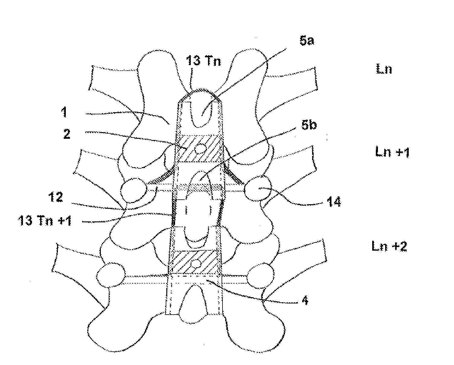
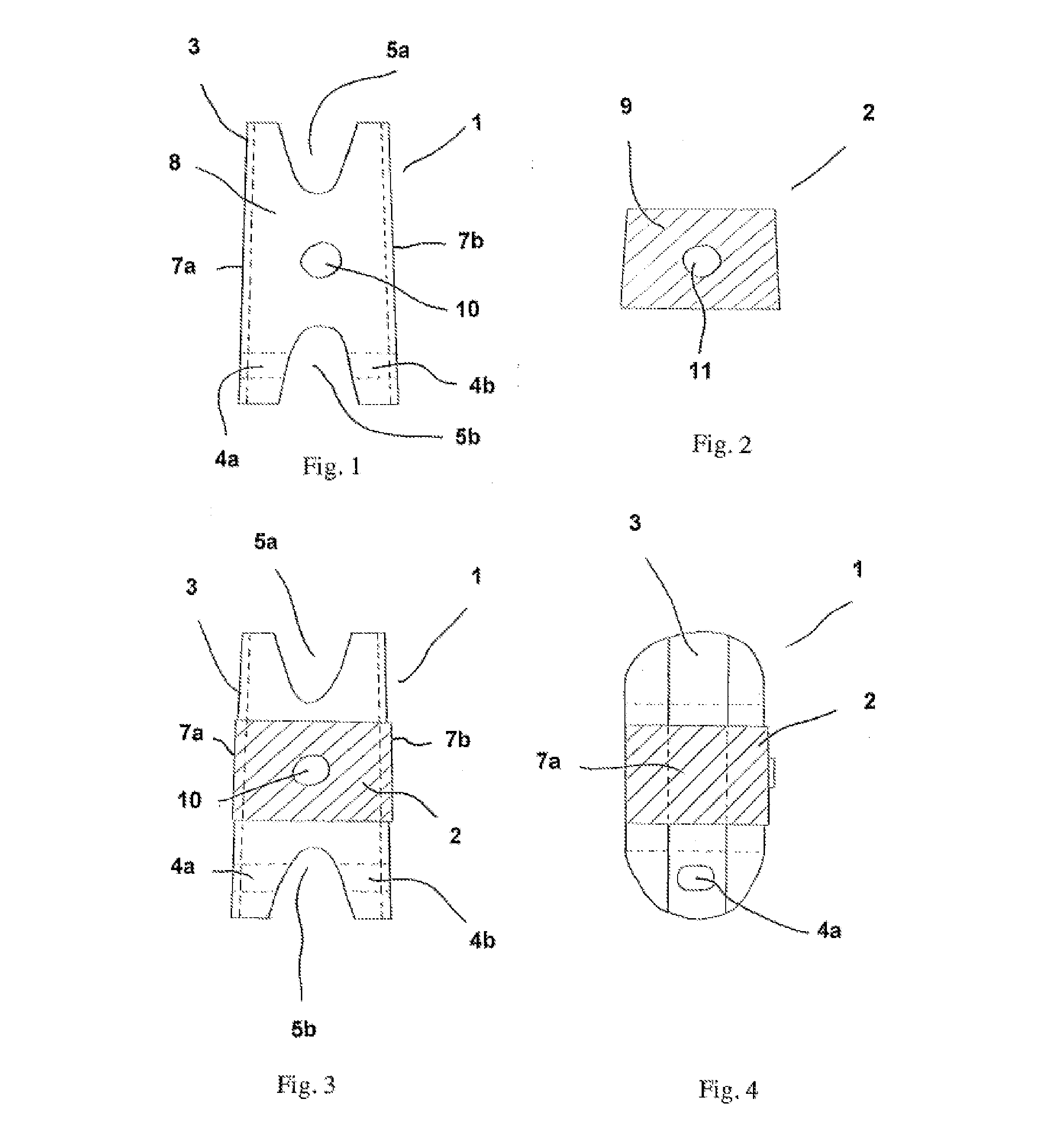
[0043]FIG. 1 shows an example of an intervertebral wedge 1 according to the invention, in a view of its back face 8. Shaped as a slightly conical X with a cranial width substantially less than its caudal width, it has two notches 5a and 5b in the cranial and caudal portions respectively. A hole 10 is provided at the center of the wedge to allow attaching the rigid strip 2. The material chosen in this example is PEEK.

[0044]FIG. 2 shows an example of a rigid strip 2 according to the invention, in a view of its back face 9. Having a shape complementary to the intervertebral wedge 1, it partly covers the back face 8 of the latter as well as part of the two lateral faces 7a and 7b. It also has a hole 11, positioned so as be superimposed over the hole 10 present in the intervertebral wedge 1 to allow screw attachment of the rigid strip 2. The material chosen in this example is a biocompatible metal.

[0045]FIG. 3 shows the intervertebral wedge 1 covered by the rigid strip 2 according to the...


PUM


Abstract

The invention concerns an intervertebral dynamic fixation implant intended for stabilization of the lumbar spine in one or more intervertebral segments, comprising: an intervertebral wedge extending along a vertical axis, comprising two craniocaudal notches intended for receiving the spinous processes of two lumbar vertebrae Ln and Ln+1, a vertical channel being arranged on the two lateral faces of said intervertebral wedge, a rigid strip covering a portion of the back face and of the two lateral faces of the intervertebral wedge, so as to leave a passageway in the vertical side channels, at least one hole passing through the intervertebral wedge from one lateral face to the other, in the caudal portion of the rigid strip, two pedicle screws fixed to the lumbar vertebra Ln+1, comprising a system for tensioning and attaching a braid Tn which wraps around the spinous process of lumbar vertebra Ln and passes through the passageways of the side channels of the intervertebral wedge, a rod perpendicular to the vertical axis of the intervertebral wedge, connecting the two pedicle screws by passing through said at least one hole located in the caudal portion of the rigid strip.

Description

BACKGROUND[0001]1. Technical Field[0002]The present invention relates to the field of spinal implants. It concerns an implant for retaining vertebral bodies while allowing a sufficient degree of freedom to permit movement of the spine in all three planes.[0003]2. Description of the Related Art[0004]In the musculoskeletal system, the spine acts to stabilize the trunk and to support the pectoral and pelvic girdles. These functions can be altered by natural wear, pathological degeneration, or traumatic shock, resulting in discomfort, pain, or even severe disability in subjects suffering from these disorders.[0005]The effectiveness of the load distribution and the load balancing, both static and mobile, are determined by coordinating the various component segments of the spine, divided into functional units. Each functional unit consists of two adjacent vertebrae connected by an intervertebral disc. Stacked atop one another, they form the spinal joint complex.[0006]Various surgical tech...

Claims


Application Information

Patent Timeline
Patent Type & Authority Applications(United States)
IPC IPC(8): A61B17/70
CPCA61B17/7067
Inventor DUBOIS, GILLESSENEGAS, JACQUES
Owner DUBOIS GILLES
Why Eureka
Try Eureka