Receiver tank purge in vapor compression cooling system with pumped refrigerant economization

a technology of vapor compression and economization of refrigerant, which is applied in the field of high-efficiency cooling systems, can solve the problems that the free cooling coil assembly does not provide 100% sensible cooling, and achieve the effects of reducing pump performance, more stability, and more reliable operation

Active Publication Date: 2014-06-12
VERTIV CORP
View PDF4 Cites 32 Cited by
  • Summary
  • Abstract
  • Description
  • Claims
  • Application Information

AI Technical Summary

Problems solved by technology

The second or free cooling coil assembly does not provide 100% sensible cooling and has an airside pressure drop similar to the evaporator (which is the first cooling coil assembly).

Method used


Image

  • Receiver tank purge in vapor compression cooling system with pumped refrigerant economization
  • Receiver tank purge in vapor compression cooling system with pumped refrigerant economization
  • Receiver tank purge in vapor compression cooling system with pumped refrigerant economization

Examples


Embodiment Construction

[0024]Example embodiments will now be described more fully with reference to the accompanying drawings.

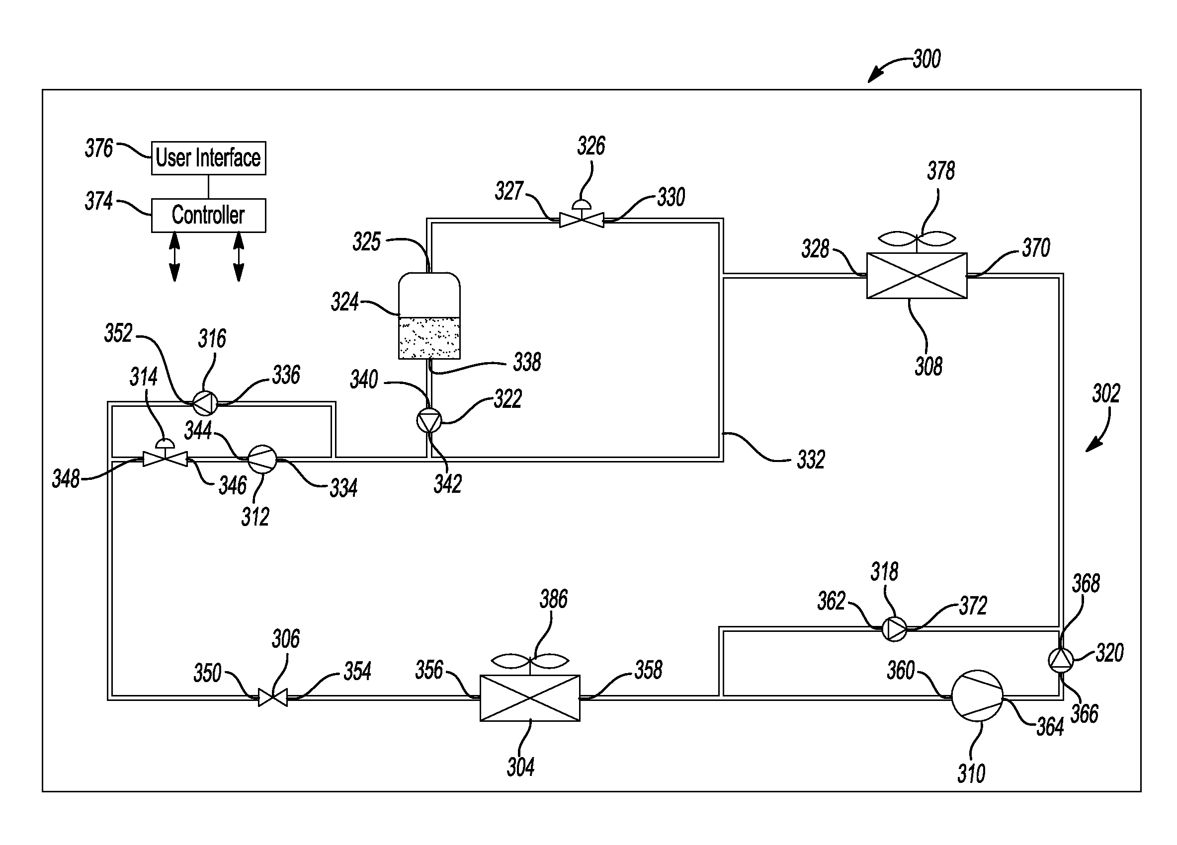
[0025]In accordance with an of the present disclosure, a cooling system, which may include a CRAC, includes a DX cooling circuit with a pumped refrigerant economizer and a receiver / surge tank enabling the system to be run in a pumped refrigerant economizer mode when the temperature outside is cold enough to cool the cooling fluid circulating in the cooling circuit and bypass the compressor. The cooling fluid may illustratively be a phase change refrigerant having a vapor phase and a liquid phase. The pumped refrigerant economizer may illustrativley include a pump that circulates the cooling fluid, illustratively the refrigerant in its liquid phase, with the compressor bypassed. This cooling system then uses the pump instead of the compressor to pump the refrigerant in its liquid phase and circulate the refrigerant when the outside air temperature is low enough to provide the heat e...


PUM


Abstract

A cooling system includes a cooling circuit having an evaporator, a condenser, a compressor, an expansion device, a liquid pump, and a receiver / surge tank coupled between the condenser and the liquid pump. The cooling system has a direct expansion mode and a pumped refrigerant economizer mode. When the cooling system switches from the direct expansion mode to the pumped refrigerant economizer mode, refrigerant is flushed from the refrigerant / surge tank so that the cooling circuit is overcharged when it begins operating in the pumped refrigerant economizer mode.

Description

CROSS-REFERENCE TO RELATED APPLICATIONS[0001]This application claims the benefit of U.S. Provisional Application No. 61 / 734,416 filed on Dec. 7, 2012. The entire disclosure of the above application is incorporated herein by reference.FIELD[0002]The present disclosure relates to cooling systems, and more particularly, to high efficiency cooling systems. BACKGROUND[0003]This section provides background information related to the present disclosure which is not necessarily prior art.[0004]Cooling systems have applicability in a number of different applications where fluid is to be cooled. They are used in cooling gas, such as air, and liquids, such as water. Two common examples are building HVAC (heating, ventilation, air conditioning) systems that are used for “comfort cooling,” that is, to cool spaces where people are present such as offices, and data center climate control systems.[0005]A data center is a room containing a collection of electronic equipment, such as computer servers...

Claims


Application Information

Patent Timeline
Patent Type & Authority Applications(United States)
IPC IPC(8): F25B49/02F25B41/20
CPCF25B49/02F25B23/00F25B45/00F25B2400/0401F25B2400/0415F25B2400/16F25B2400/19F25B2600/13Y02B30/70
Inventor SCHRADER, TIMOTHY J.HAGGY, GREGSILLATO, STEPHEN
Owner VERTIV CORP
Why Eureka
Try Eureka