Method and apparatus for controlling a solenoid actuated inlet valve

a solenoid and inlet valve technology, applied in the direction of electric control, piston pumps, positive displacement liquid engines, etc., can solve the problems of pressure shock, engine noise, fuel pump relatively noisy, etc., and achieve the effect of reducing engine nois

Active Publication Date: 2014-06-12
HITACHI LTD
View PDF9 Cites 10 Cited by
  • Summary
  • Abstract
  • Description
  • Claims
  • Application Information

AI Technical Summary

Benefits of technology

[0016]The present invention provides both a method and apparatus for controlling the actuator for a solenoid ...

Problems solved by technology

One disadvantage of direct injection engines is that the fuel pumps are relatively noisy, espec...

Method used


Image

  • Method and apparatus for controlling a solenoid actuated inlet valve
  • Method and apparatus for controlling a solenoid actuated inlet valve
  • Method and apparatus for controlling a solenoid actuated inlet valve

Examples


Embodiment Construction

Embodiments of the Present Invention

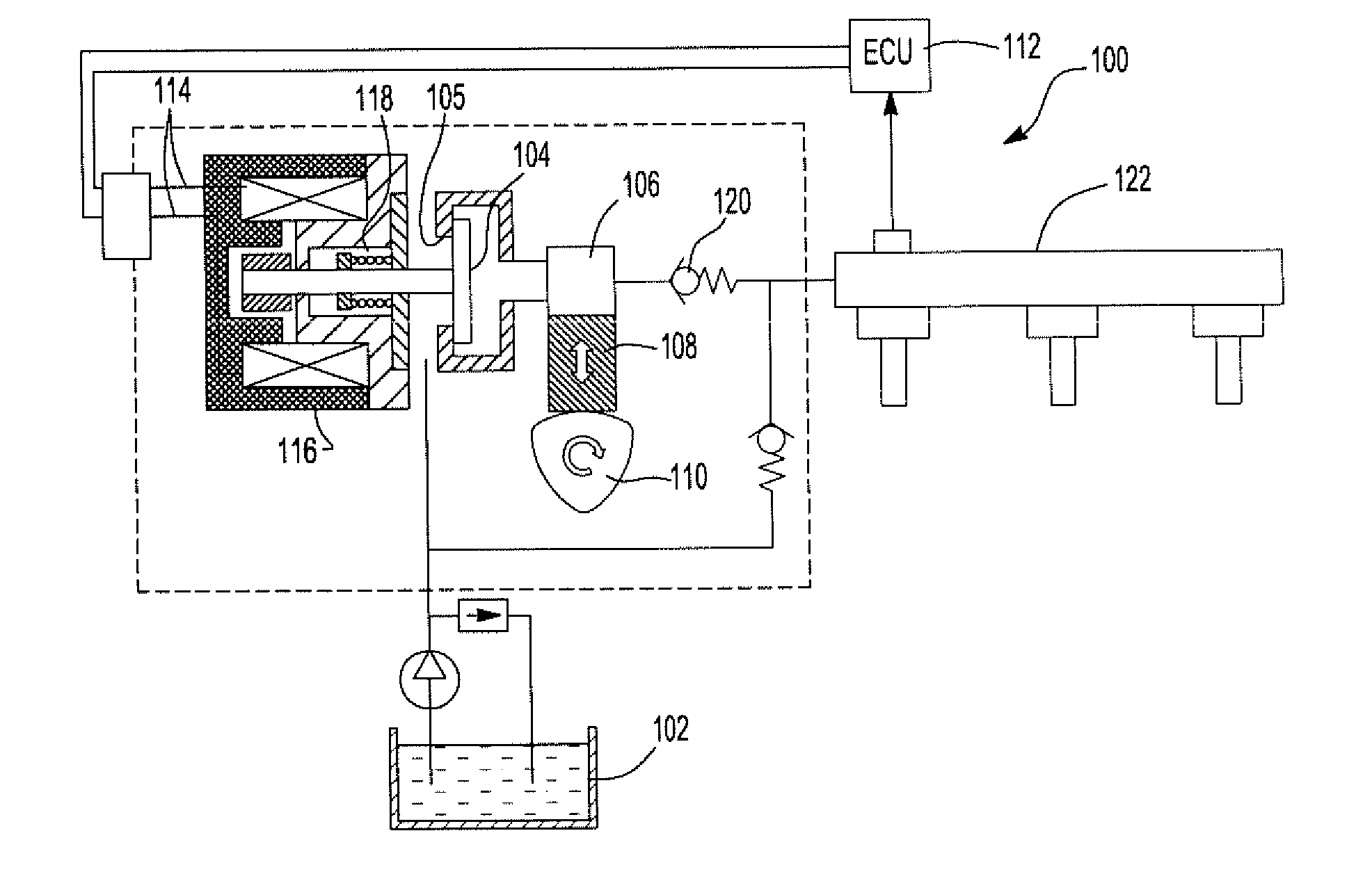
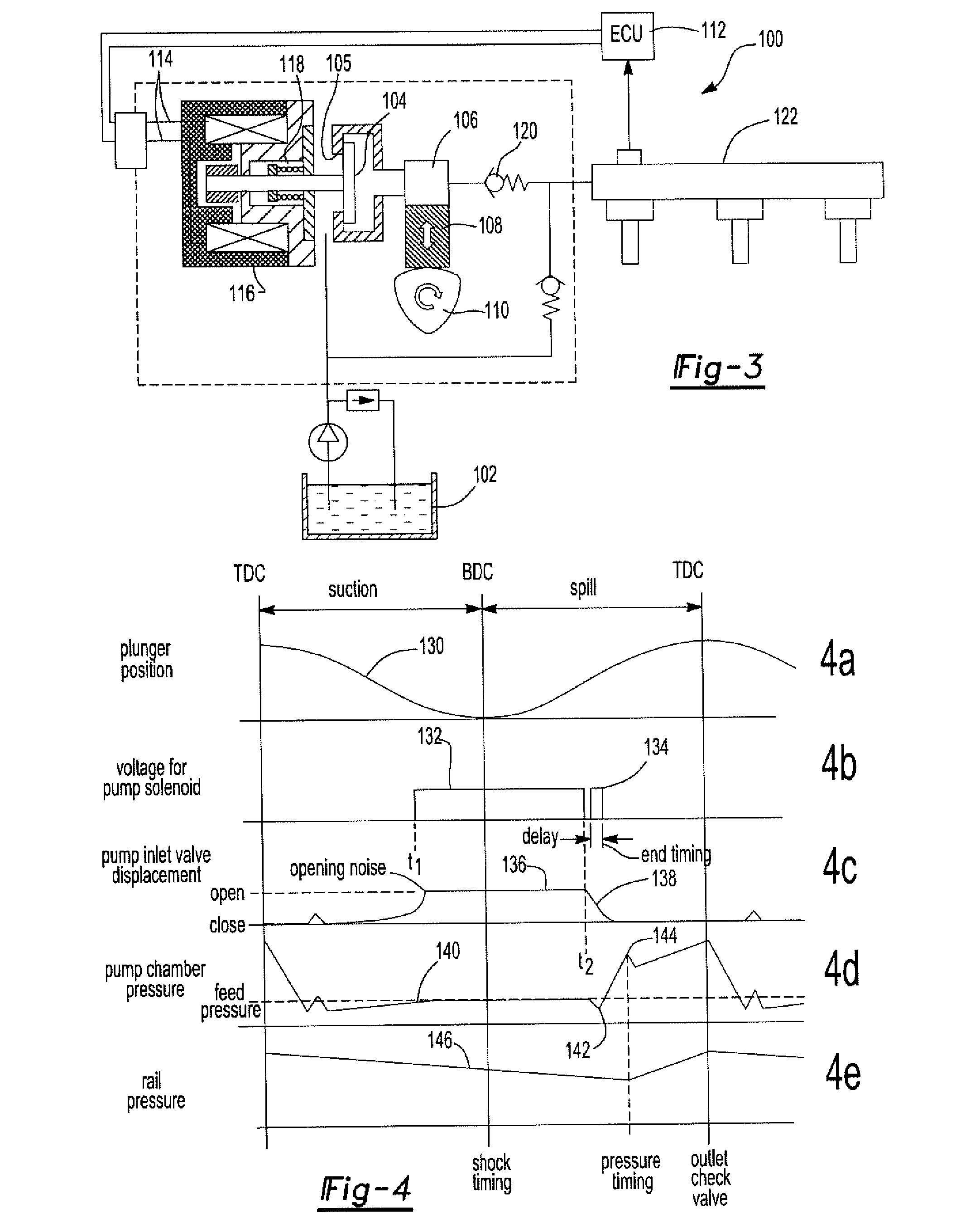
[0036]With reference first to FIG. 3, an exemplary fuel pumping system 100 is illustrated. Like the previously described systems, the fuel system 100 includes a fuel tank 102 which is fluidly connected through a port 105 and a fuel inlet valve 104 to a pump chamber 106. A piston 108 is reciprocally driven in the pump chamber by a rotating cam 110 which rotates in synchronism with the engine crankshaft or output shaft (not shown).

[0037]An electronic control circuit 112, which preferably included a programmed processor, is electrically connected to the input terminals 114 of a solenoid 116 mechanically connected to the inlet valve 104. Upon energization of the solenoid 116, the solenoid moves the valve to its open position. Conversely, upon de-energization of the solenoid 116, a spring 118 returns the valve 104 to its closed position. In addition, a one way outlet valve 120 fluidly connects the pump chamber 106 to a fuel rail 122 of an automotive in...


PUM


Abstract

A method and apparatus for controlling a solenoid actuated inlet valve to a pump chamber of a piston pump. A control circuit energizes the solenoid to open the inlet valve in synchronism with the reciprocation of the piston and thereafter de-energize the solenoid to initiate closure of the inlet valve. The inlet valve is decelerated following de-energization of the solenoid thus effectively reducing engine noise attributable to the inlet valve.

Description

BACKGROUND OF THE INVENTION[0001]1. Field of the Invention[0002]The present invention relates generally to fuel pumps and, more particularly, to a method and apparatus for controlling a solenoid actuated inlet valve of a fuel pump to thereby reduce engine noise.[0003]2. Description of Relevant Art[0004]Direct fuel injection internal combustion engines have enjoyed increasing popularity in the automotive industry. Such direct injection internal combustion engines enjoy improved fuel economy and engine performance as contrasted with other types of automotive internal combustion engines.[0005]In a direct fuel injection internal combustion engine, the fuel injector is open directly to the internal combustion chamber of the engine rather than upstream from the air intake valves. As such, the direct fuel injection internal combustion engine must generate relatively high fuel injection pressures in order to overcome the high pressures present in the internal combustion chamber during the f...

Claims


Application Information

Patent Timeline
IPC IPC(8): F16K31/06
CPCF02M59/466F16K31/0655F02D41/3845F02D2041/2055F02D2041/2068F02D2200/025F02D2200/0602F02M59/367Y10T137/0318F04B7/0076
Inventor TANABE, YOSUKEMCCUNE, DONALD J.
Owner HITACHI LTD
Why Eureka
Try Eureka