Apparatus having universal structure for driving a plurality of LED strings

a technology of led strings and universal structure, which is applied in the direction of lighting devices, electrical devices, light sources, etc., can solve the problems of reducing efficiency, costing more, and difficult to miniaturize led-based lighting devices, and achieve the effect of efficient driving

Inactive Publication Date: 2014-06-12
VASTVIEW TECH
View PDF13 Cites 36 Cited by
  • Summary
  • Abstract
  • Description
  • Claims
  • Application Information

AI Technical Summary

Benefits of technology

[0013]The present invention has been made to provide an apparatus that can efficiently drive an LED-based lighting apparatus to accommodate different voltage levels of different input AC voltage sources. In accordance with the present invention, the LED-based lighting apparatus comprises a universal structure for driving a plurality of controllable LED strings that can be connected in series, parallel or by-passed based on the automatically detected input voltage range. In addition, the number of LEDs connected in series in each controllable LED string can further be adjusted as the input voltage varies with time.

Problems solved by technology

The need of a voltage conversion device reduces the efficiency, costs more and also makes it difficult to miniaturize an LED-based lighting device.
If the method of driving the LED lighting strings only relies on changing the number of LEDs connected in series to adapt to different levels of input voltage, the utilization of LEDs becomes very low when the input voltage is low.

Method used


Image

  • Apparatus having universal structure for driving a plurality of LED strings
  • Apparatus having universal structure for driving a plurality of LED strings
  • Apparatus having universal structure for driving a plurality of LED strings

Examples


second embodiment

[0063]In accordance with the present invention, in the second embodiment the controller 240 also controls the plurality of switching units 211 by using the parallel-connection and series-connection signals to change the state of each switching unit 211 and adjusts the current of the current source 230 that flows through the plurality of controllable LED strings 201 based on the voltage level of the input voltage VIN. In addition, for a given voltage range of the input voltage VIN, the controller 240 further uses the controlling signals to control the number of LEDs connected in series in each controllable LED string.

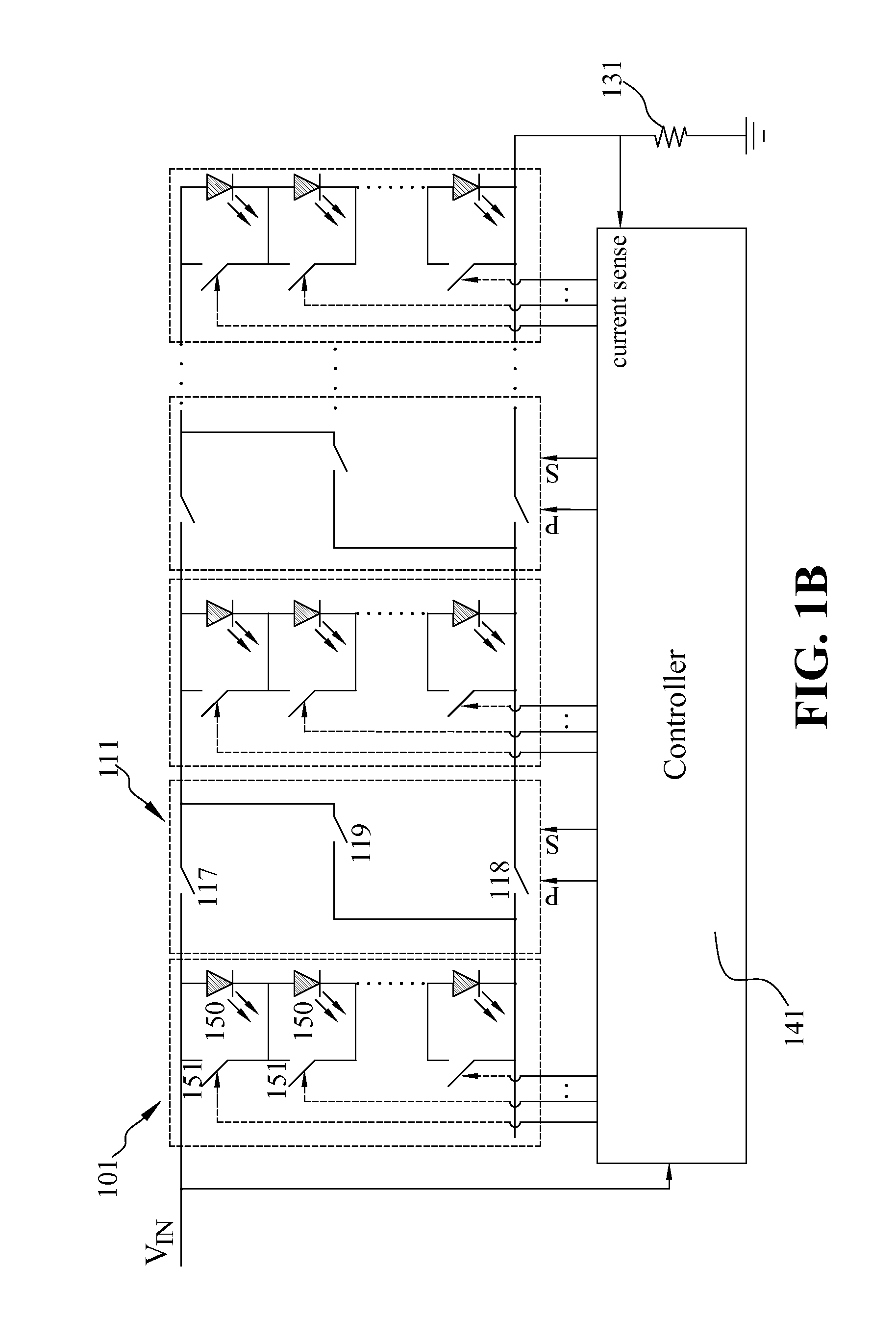
[0064]Similar to FIG. 1B which is varied from FIG. 1A by replacing the current source 130 with a resistor 131, FIG. 2B is varied from FIG. 2A by replacing the current source 230 with a resistor 231. As a result, the controller 241 in the apparatus of FIG. 2B can control the plurality of switching units 211 by using the parallel-connection and series-connection signals to...

third embodiment

[0067]In accordance with the present invention, in the third embodiment the controller 340 also controls the plurality of switching units 311 by using the parallel-connection and series-connection signals to change the state of each switching unit 311 and adjusts the current of the current source 330 that flows through the plurality of controllable LED strings 301 based on the voltage level of the input voltage VIN. In addition, for a given voltage range of the input voltage VIN, the controller 340 further uses the controlling signals to control the number of LEDs connected in series in each controllable LED string.

[0068]Similar to FIG. 2B which is varied from FIG. 2A by replacing the current source 230 with a resistor 231, FIG. 3B is varied from FIG. 3A by replacing the current source 330 with a resistor 331. As a result, the controller 341 in the apparatus of FIG. 3B can control the plurality of switching units 311 by using the parallel-connection and series-connection signals to ...

fourth embodiment

[0076]In the present invention, the apparatus further includes a switching voltage comparator unit 780 that sends a few common signals 785 to each LED controlling circuit 751. Each LED controlling circuit 751 receives an input propagation signal 752 and sends out an output propagation signal 753 to the next LED controlling circuit as shown in FIG. 7A.

[0077]As can also be seen in FIG. 7A, the first LED controlling circuit connected in parallel with the LED on the top in the left most controllable LED string receives a forward propagation signal 781 from the switching voltage comparator unit 780. The output propagation signal 753 is propagated from the first LED controlling circuit to the next LED controlling circuit which again propagates the propagation signal to the following LED controlling circuit, and so on.

[0078]As shown in FIG. 7A, the forward multiplexer 760 in the left most controllable LED string multiplexes the forward propagation signal 781 sent from the switching voltage...


PUM


Abstract

An apparatus comprises a plurality of controllable LED strings interposed with a plurality of switching units with each switching unit being connected between a leading controllable LED string and a trailing controllable LED string. A controller controls the switching units so that controllable LED strings are connected in a combination of series and parallel connections by connecting two adjacent leading and trailing controllable LED strings in series or parallel or by-passing the leading controllable LED string based on an automatically detected input voltage range. Each controllable LED string includes a plurality of LEDs connected in series between positive and negative ends of the controllable LED string and a plurality of controlling switches each corresponding to an LED. The number of LEDs connected in series in each controllable LED string is further adjusted by the controller as the input voltage varies with time.

Description

BACKGROUND OF THE INVENTION[0001]1. Field of the Invention[0002]The present invention relates generally to light emitting diode (LED) based lighting apparatuses, and more particularly to an apparatus for driving a plurality of controllable LED strings.[0003]2. Description of Related Arts[0004]LEDs are semiconductor-based light sources often employed in low-power instrumentation and appliance applications for indication purposes. The application of LEDs in various lighting units has become more and more popular. For example, high brightness LEDs have been widely used for traffic lights, vehicle indicating lights, and braking lights.[0005]An LED has an I-V characteristic curve similar to an ordinary diode. When the voltage applied to the LED is less than a forward voltage, only very small current flows through the LED. When the voltage exceeds the forward voltage, the current increases sharply. The output luminous intensity of an LED light is approximately proportional to the LED curr...

Claims


Application Information

Patent Timeline
Patent Type & Authority Applications(United States)
IPC IPC(8): H05B33/08H05B44/00
CPCH05B33/083H05B45/44H05B45/48
Inventor CHU, HUNG-CHISHEN, YUH-REN
Owner VASTVIEW TECH
Why Eureka
Try Eureka