Switching power supply device

a power supply device and power supply technology, applied in the direction of power conversion systems, dc-dc conversion, climate sustainability, etc., can solve the problems of increasing loss, difficult to obtain output differential signals, and large devices, and achieve simple and inexpensive control circuits, high speed response characteristics, and the effect of reducing the influence of an operation delay of the control circui

Active Publication Date: 2014-06-12
COSEL
View PDF4 Cites 2 Cited by
  • Summary
  • Abstract
  • Description
  • Claims
  • Application Information

AI Technical Summary

Benefits of technology

[0023]The switching power supply device of the present invention calculates the ON and OFF time and the like so as to satisfy the control function described above on the basis of two signals, i.e., an input voltage signal and an output voltage signal, which are detected values, and controls ON and OFF of the main switching element. Therefore, high speed response characteristics to a sudden change in external environments of the power supply device can be implemented by a simple and inexpensive control circuit.
[0024]Further, by employing a configuration in which an output voltage signal is estimated using a state variable estimation means, an influence of an operation delay of the control circuit can be minimized even if an inexpensive and low-speed microcomputer is used. Further, by employing a configuration in which the state variable estimation means also estimates a signal corresponding to an output current (for example, the voltage drop component), control in consideration of an influence of parasitic impedance on a path in which the output current flows becomes possible and thus precision in output voltage control can be improved.
[0025]Further, by employing a configuration in which parameter estimation is performed about a circuit constant initially set as a default value and the circuit constant is updated periodically, influences of an individual difference of the impedance of each circuit device (a resistance value, inductance, capacitance, conduction resistance of semiconductors and the like), a temperature change and variation with time are reliably canceled. Therefore, output voltage control can be performed more precisely.

Problems solved by technology

However, in the case of the switching power supply device of PTL 1, both the input voltage signal and the output voltage signal are obtained by simply digitizing analog information of the input voltage and the output voltage by an A / D converter and thus it is not easy to obtain the output differential signal.
There is therefore a problem that the power supply device becomes large in size and that loss increases.
In a method in which an output voltage signal digitized by an A / D converter is differentiated to obtain an output differential signal, a delay in control due to an increase in the number of times of calculation becomes a problem.

Method used


Image

  • Switching power supply device
  • Switching power supply device
  • Switching power supply device

Examples


second embodiment

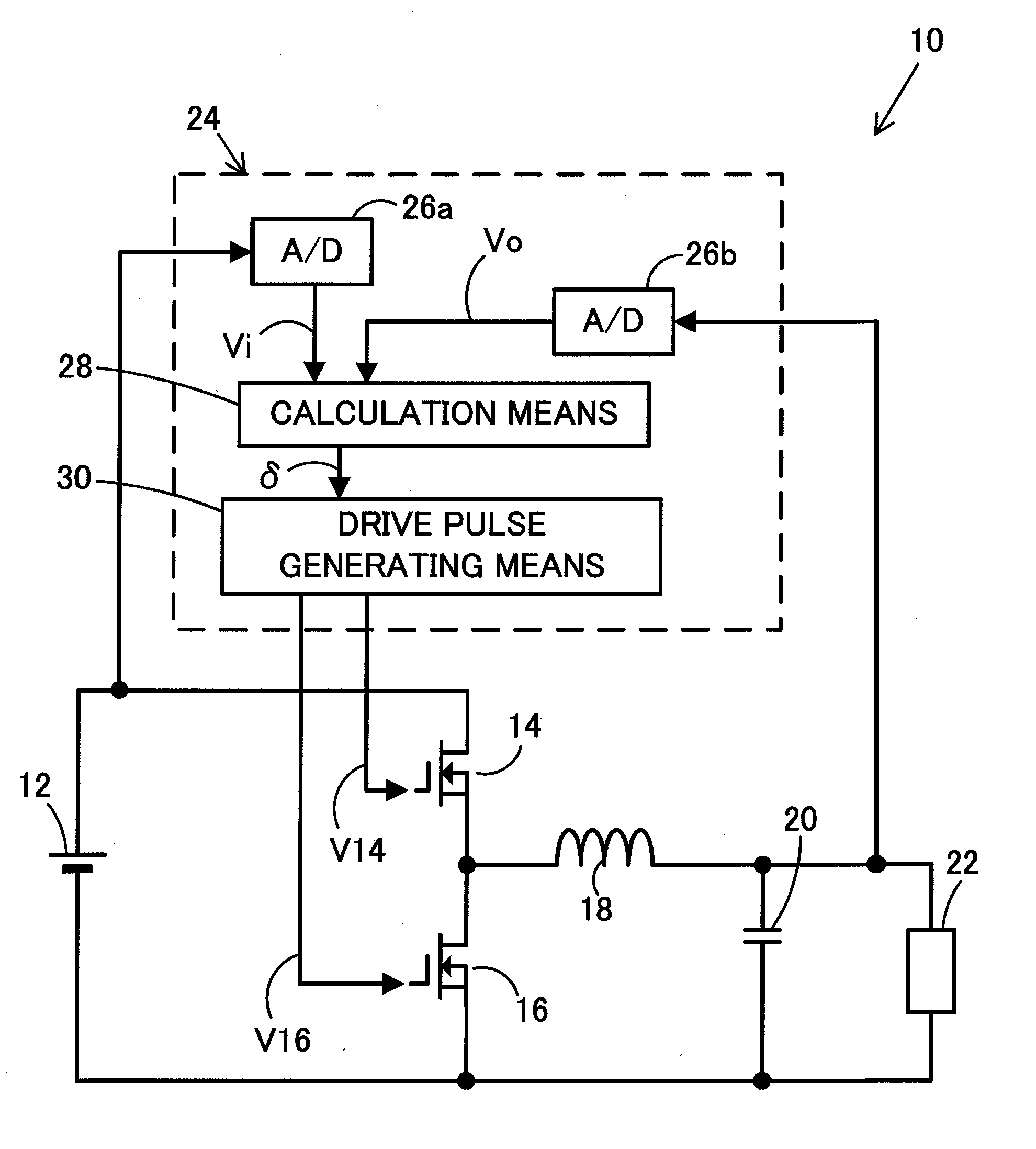
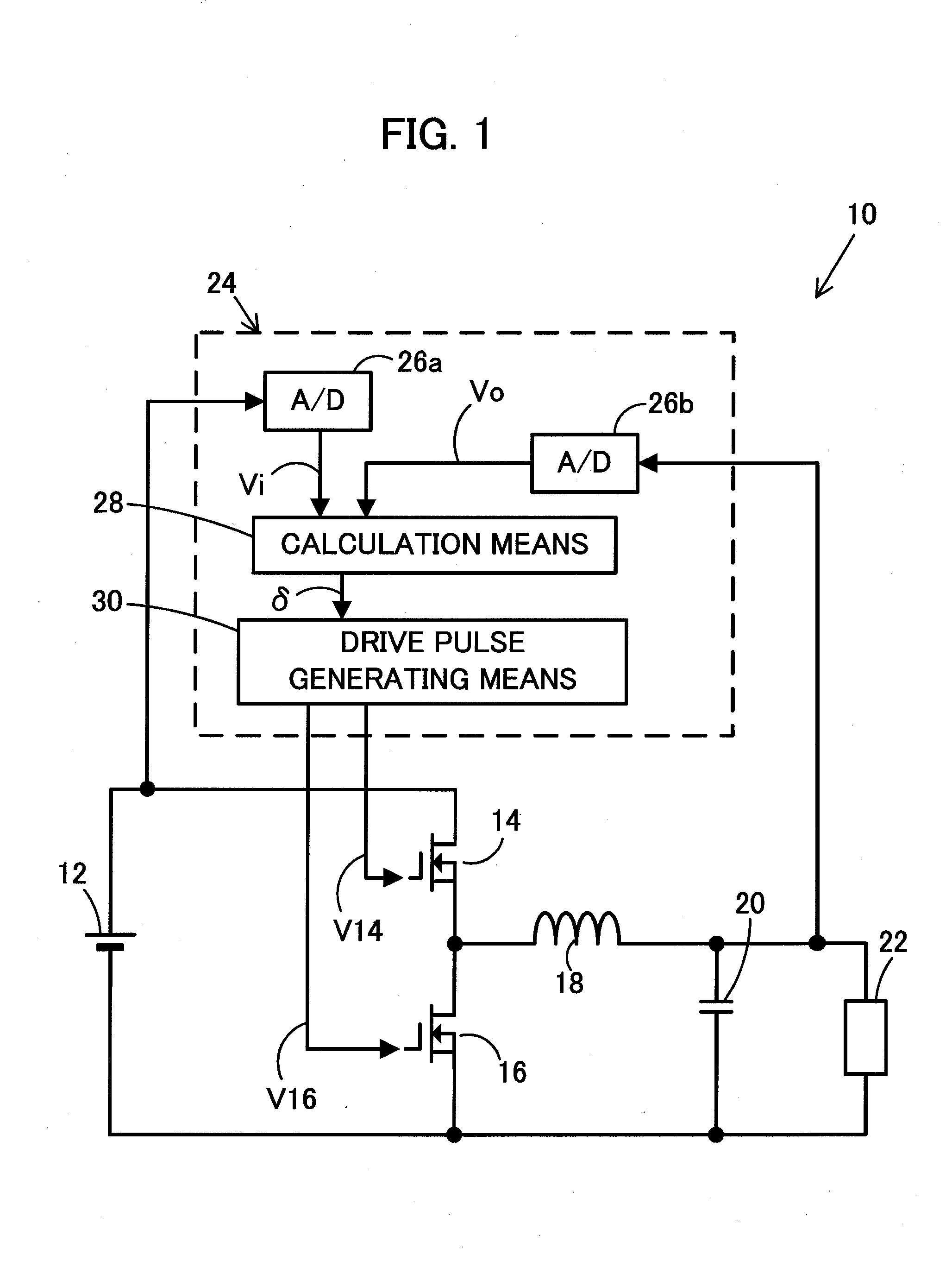
[0090]Next, a switching power supply device 40 of the present invention will be described with reference to FIGS. 6 and 7. Here, components similar to those of the above-described switching power supply device 10 will be denoted by similar reference numerals and description thereof will be omitted. The switching power supply device 40 has a configuration substantially similar to that of the switching power supply device 10 illustrated in FIG. 1 except that A / D converters 42a and 42b, a calculation means 44 and a drive pulse generating means 46 are provided instead of the A / D converters 26a and 26b, the calculation means 28 and the drive pulse generating means 30. The A / D converters 42a and 42b, the calculation means 44 and the drive pulse generating means 46 behave differently from the A / D converters 26a and 26b, the calculation means 28 and the drive pulse generating means 30, respectively.

[0091]Analog information from each component is input in the A / D converters 42a and 42b, whic...

third embodiment

[0096]Next, a switching power supply device 50 of the present invention will be described with reference to FIGS. 8 to 10. Here, components similar to those of the above-described switching power supply device 10 will be denoted by similar reference numerals and description thereof will be omitted. The switching power supply device 50 has a configuration substantially similar to that of the switching power supply device 10 illustrated in FIG. 1 except that A / D converters 52a and 52b, a calculation means 54 and a drive pulse generating means 56, which behave differently, are provided instead of the A / D converters 26a and 26b, the calculation means 28 and the drive pulse generating means 30. The A / D converters 52a and 52b, the calculation means 54 and the drive pulse generating means 56 behave differently from the A / D converters 26a and 26b, the calculation means 28 and the drive pulse generating means 30, respectively.

[0097]Analog information from each component is input in the A / D c...

fourth embodiment

[0107]Next, a switching power supply device 60 of the present invention will be described with reference to FIGS. 11 to 13. Here, components similar to those of the above-described switching power supply device 10 will be denoted by similar reference numerals and description thereof will be omitted. The switching power supply device 60 has a configuration substantially similar to that of the switching power supply device 10 illustrated in FIG. 1 except that A / D converters 62a and 62b, a calculation means 64 and a drive pulse generating means 66, which behave differently, are provided instead of the A / D converters 26a and 26b, the calculation means 28 and the drive pulse generating means 30. The A / D converters 62a and 62b, the calculation means 64 and the drive pulse generating means 66 behave differently from the A / D converters 26a and 26b, the calculation means 28 and the drive pulse generating means 30, respectively.

[0108]Analog information from each component is input in the A / D ...


PUM


Abstract

A control circuit (24) includes a calculation means (28) which determines ON time and OFF time of a main switching element (14) and a drive pulse generating means (30) which generates drive pulses that turn the main switching element (14) ON and OFF. A control function formula which prescribes a relationship between an output voltage (Vo) and an output differential value (Vd) by a negative linear function and the like is defined in the calculation means (28). The calculation means (28) samples an input voltage signal (Vi) and an output voltage signal (Vo) at a timing synchronized with a switching cycle of the main switching element (14), and calculates the ON time and OFF time of the main switching element (14) thereafter so as to satisfy the control function formula. The drive pulse generating means (30) generates drive pulses (V14) which turn the main switching element (14) ON and OFF on the basis of the ON and OFF time determined by the calculation means (28).

Description

BACKGROUND OF THE INVENTION[0001]1. Field of the Invention[0002]The present invention relates to a switching power supply device which stabilizes an output voltage using a digital control circuit.[0003]2. Description of the Related Art[0004]In a related art switching power supply device, an output voltage is stabilized by, for example, pulse width modulation (PWM) control or pulse frequency modulation (PFM) control using a highly intelligent digital control circuit with, for example, a digital processor. Especially recently, it is urgently required to reduce a transient fluctuation in an output voltage in response to a sudden change in an external environment of the power supply device.[0005]Exemplary situations of sudden changes in an external environment of the switching power supply device may include a sudden change in an input voltage during operation or a sudden increase or decrease in an output current in response to a change in a state of a load. A starting operation of the ...

Claims


Application Information

Patent Timeline
Patent Type & Authority Applications(United States)
IPC IPC(8): H02M3/158
CPCH02M3/158H02M3/157Y02B70/10
Inventor USUDA, TAKESHIMATSUO, YOSHIKI
Owner COSEL
Why Eureka
Try Eureka