Eureka AIR delivers breakthrough ideas for toughest innovation challenges, trusted by R&D personnel around the world.

Method and apparatus for estimating response characteristic, and receiving method and receiver utilizing the same

a response characteristic and estimation method technology, applied in the direction of synchronisation signal speed/phase control, amplitude demodulation, baseband system details, etc., can solve the problems of general degradation of receiving characteristics and the inability of technology utilizing correlation processing to track environmental changes, so as to improve the estimation accuracy of frequency offset, reduce the degradation of response characteristic estimation accuracy, and simplify the arithmetic circuit

Inactive Publication Date: 2009-03-10
HERA WIRELESS
View PDF21 Cites 2 Cited by
  • Summary
  • Abstract
  • Description
  • Claims
  • Application Information

AI Technical Summary

Benefits of technology

[0007]The inventor of the present invention has made the present invention in view of the foregoing circumstances and an object thereof is to provide a response characteristic estimation apparatus which estimates response characteristic at high speed with a simple arithmetic circuit and to provide a receiver utilizing the same. It is also an object of the present invention to provide a response characteristic estimation apparatus of which degradation in the estimation accuracy of response characteristic is reduced, wherein the degradation is caused by the frequency offset of the frequency oscillators between a transmitter and a receiver, and to provide the receiver utilizing the same. It is also an object of the present invention to provide a response characteristic estimation apparatus which can improve estimation accuracy of the frequency offset of the frequency oscillators between the transmitter and receiver and to provide the receiver utilizing the same.
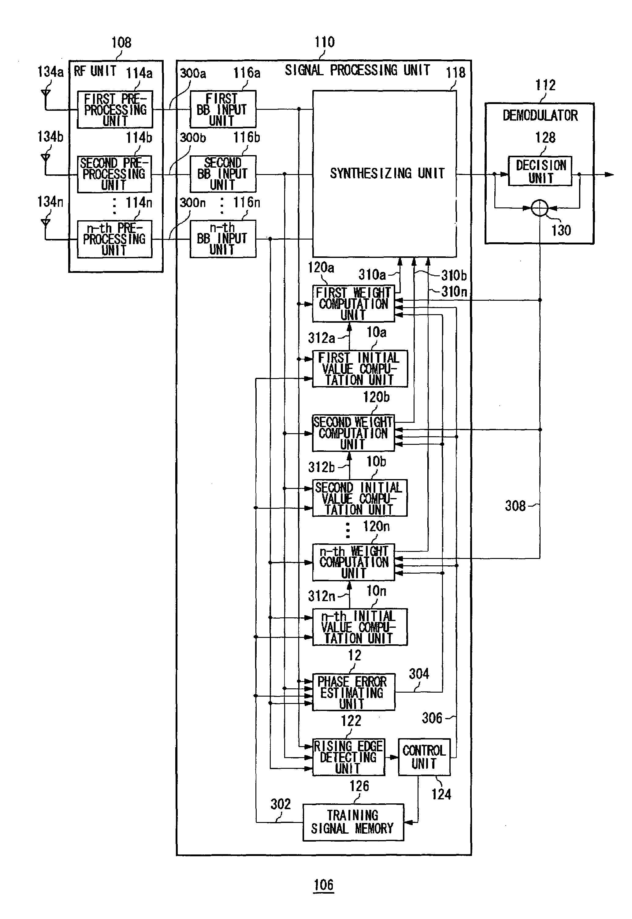
[0012]By implementing the above structure, the apparatus can estimate the response characteristic at high speed since the estimation of the phase error and the correlation processing are performed in parallel and there occurs no delay between those two processings. Moreover, the response characteristic can be estimated with high accuracy since the result of the correlation processing is compensated utilizing the estimated phase error.

Problems solved by technology

However, unlike the adaptive algorithm, the technology utilizing the correlation processing can not track an environmental change.
If the weighting coefficient including an error is utilized in the adaptive array antenna technology, receiving characteristic generally degrades.

Method used


Image

  • Method and apparatus for estimating response characteristic, and receiving method and receiver utilizing the same
  • Method and apparatus for estimating response characteristic, and receiving method and receiver utilizing the same
  • Method and apparatus for estimating response characteristic, and receiving method and receiver utilizing the same

Examples


first embodiment

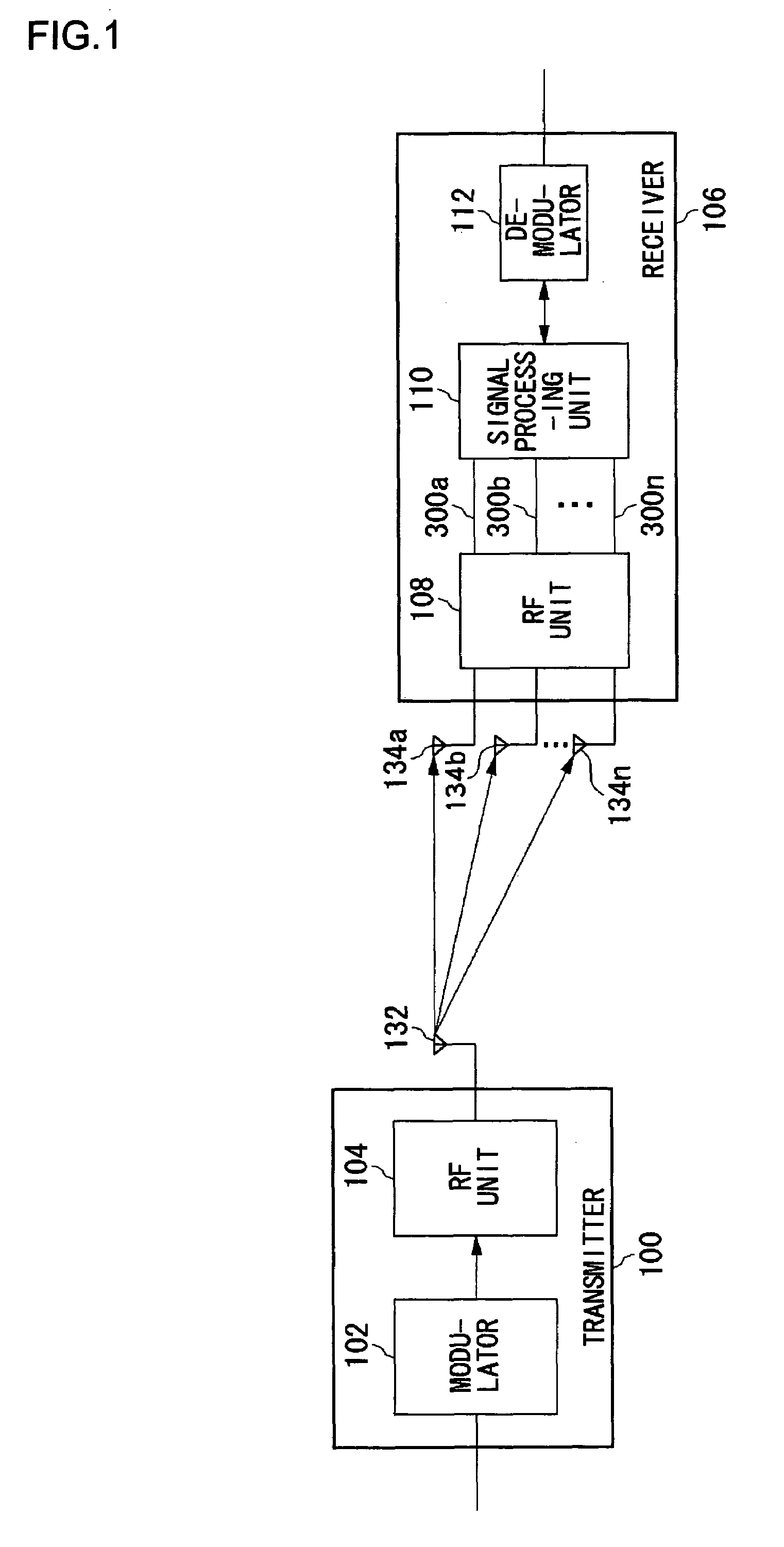
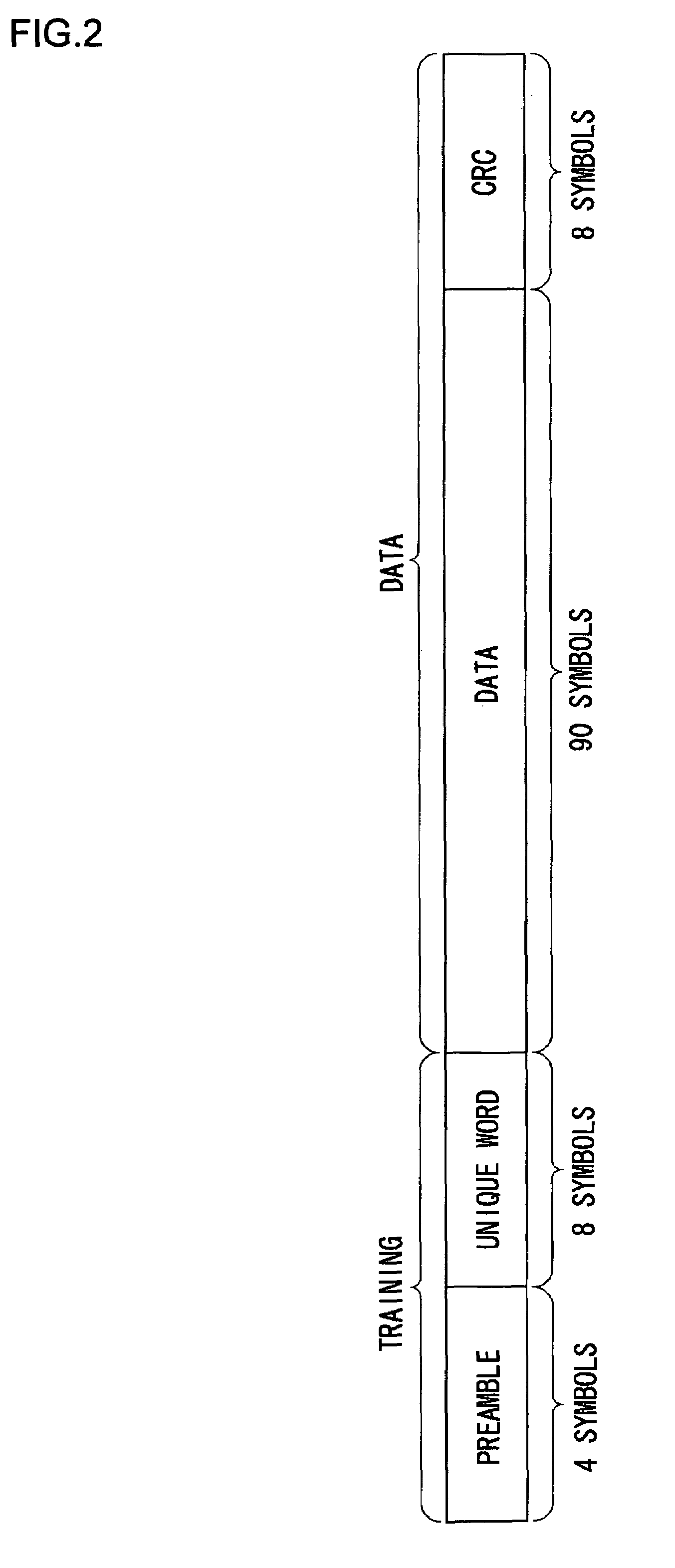
[0045]The first embodiment of the present invention relates to a receiver provided with an adaptive array antenna which receives radio signals with a plurality of antennas as burst signals and synthesizes the received signals with weighting them respectively by different weighting coefficients. The burst signal is composed of a known training signal which is disposed in the head part thereof and a data signal. The receiver according to the first embodiment, in a training signal interval, performs a correlation processing based on the training signal and the received signal and estimates frequency offset between frequency oscillators of a transmitter and the receiver. The correlation processing and the estimation of the frequency offset are performed in parallel. Initial response characteristics of the plurality of received signals to the transmission signal are acquired respectively by compensating the results of the correlation processings with the estimated frequency offset when t...

second embodiment

[0110]In the second embodiment, in the interval of training signal, which is included in the received signals same as in the first embodiment, the frequency offset between the frequency oscillators of the transmitter and the receiver is estimated. In the first embodiment, the frequency offset was estimated after the signal component of the training signal is eliminated from the received signal. On the other hand, in the second embodiment, where the training signal is structured by repeating signal series which has shorter frequency than the training signal, the frequency offset is estimated between same signals which appear in a cyclic manner because of the repetition. Therefore, it is not required to eliminate the signal component of the training signal from the received signal and the multiplication unit for the elimination becomes unnecessary.

[0111]FIG. 15 shows the structure of a phase error estimating unit 12 according to the second embodiment. The phase error estimating unit 1...

third embodiment

[0113]In the third embodiment, same as in the first embodiment and the second embodiment, the frequency offset between the frequency oscillators of the transmitter and the receiver is estimated. In the first and second embodiments, the frequency offset is estimated in a time axis based on the signal acquired by delaying the received signal and the received signal in the interval of the training signal. On the other hand, in the third embodiment, the received signal is converted by the Fourier transform and the frequency offset is estimated in a frequency axis based on the received signal in a frequency space. By transforming the received signal to the signal in the frequency space, the frequency offset can be estimated both in the cases where the received signal is the training signal and the received signal is the data signal. As a result, the frequency offset can be estimated more accurately in longer time than the interval of the training signal.

[0114]FIG. 16 shows the structure ...


PUM


Abstract

Baseband input units input baseband received signals. Initial value computation units compute correlation values by performing correlation processings between the baseband received signals and a training signal in the interval of the training signal. A phase error estimating unit outputs a phase error signal based on the baseband received signals arid the training signal. Weight computation units generate initial weighting coefficients by compensating the correlation values with the phase error signal, when the interval of the training signal ends. In the interval of a data signal, the weighting coefficients are updated from the initial weighting coefficients. A synthesizing unit adds up the baseband signals after weighting the baseband received signals with the weighting coefficients.

Description

BACKGROUND OF THE INVENTION[0001]1. Field of the Invention[0002]The present invention relates to a response characteristic estimation technology and a receiving technology utilizing the same. It particularly relates to a weighting coefficient estimation method and apparatus, and to receiving method and apparatus, where those methods and apparatuses are utilized for synthesizing radio signals received by a plurality of antennas.[0003]2. Description of the Related Art[0004]In wireless communication, it is in general desired to effectively use limited frequency resources. In order to use the frequency resources effectively, radio waves of same frequency are, for example, utilized as repeatedly as possible in short-range. In this case, however, communication quality degrades because of cochannel interference caused by a radio base station or mobile terminal closely located, which utilizes the same frequency. As one technology for preventing such communication quality degradation derivin...

Claims


Application Information

Patent Timeline
Patent Type & Authority Patents(United States)
IPC IPC(8): H04B7/10H04L1/02H04B7/08H04J11/00H04L1/06H04L7/04H04L25/02H04L27/00
CPCH04B7/0851H04L1/06H04L7/041H04L2027/003H04L25/0202
Inventor DOI, YOSHIHARU
Owner HERA WIRELESS
Why Eureka
Eureka Blog
Learn More