
Adaptive voltage divider with corrected frequency characteristic for measuring high voltages

a technology of frequency characteristic and voltage divider, which is applied in the direction of voltage dividers, electrical devices, multiple-port networks, etc., can solve the problems of uncontrolled changes in divider ratio, divider ratio varies in time, and divider ratios are not controlled, so as to achieve the effect of reducing the effect of cmrr

Inactive Publication Date: 2014-06-12
ACAD GORNICZO HUTNICZA IM STANISLAWA STASZICA
View PDF7 Cites 9 Cited by
  • Summary
  • Abstract
  • Description
  • Claims
  • Application Information

AI Technical Summary

Benefits of technology

The patent describes a device with two branches that can switch between different impedance levels. The device includes a circuit that can reduce interference between the two branches. The technical effect of this invention is the ability to switch between different impedance levels while minimizing interference between them.

Problems solved by technology

Firstly, the voltage divider ratio varies in time due to components ageing or ambient conditions such as temperature, humidity or environment pollution.
For instance, changes in air humidity cause changes in the leakage resistances shunting the divider impedances and thereby result in uncontrolled changes in the divider ratio.
Similarly, external pollutants (dust, fat) shunting the divider elements give rise to uncontrolled changes in the divider ratio.
Capacities of parasitic capacitances are varying in an uncontrolled manner due to the presence or relocation of extraneous conductors in the voltage divider vicinity.
Uncontrolled changes in capacity can be caused by temperature and humidity or even by air pressure influence on the air dielectric constant.
Furthermore, ageing of dielectric material also results in uncontrolled changes in capacitance.
A disadvantage of the probe according to U.S. Pat. No. 3,256,484 is the necessity for maintaining a specified amount of freon in the probe.
On the other hand, polymer insulating materials, due to unavoidable surface currents do not ensure stable capacitance and conductance parameters under varying ambient conditions (humidity, dust).
This results in an uncontrolled change in the probe both static and frequency metrological properties.

Method used


Image

  • Adaptive voltage divider with corrected frequency characteristic for measuring high voltages
  • Adaptive voltage divider with corrected frequency characteristic for measuring high voltages
  • Adaptive voltage divider with corrected frequency characteristic for measuring high voltages

Examples


first embodiment

the Invention

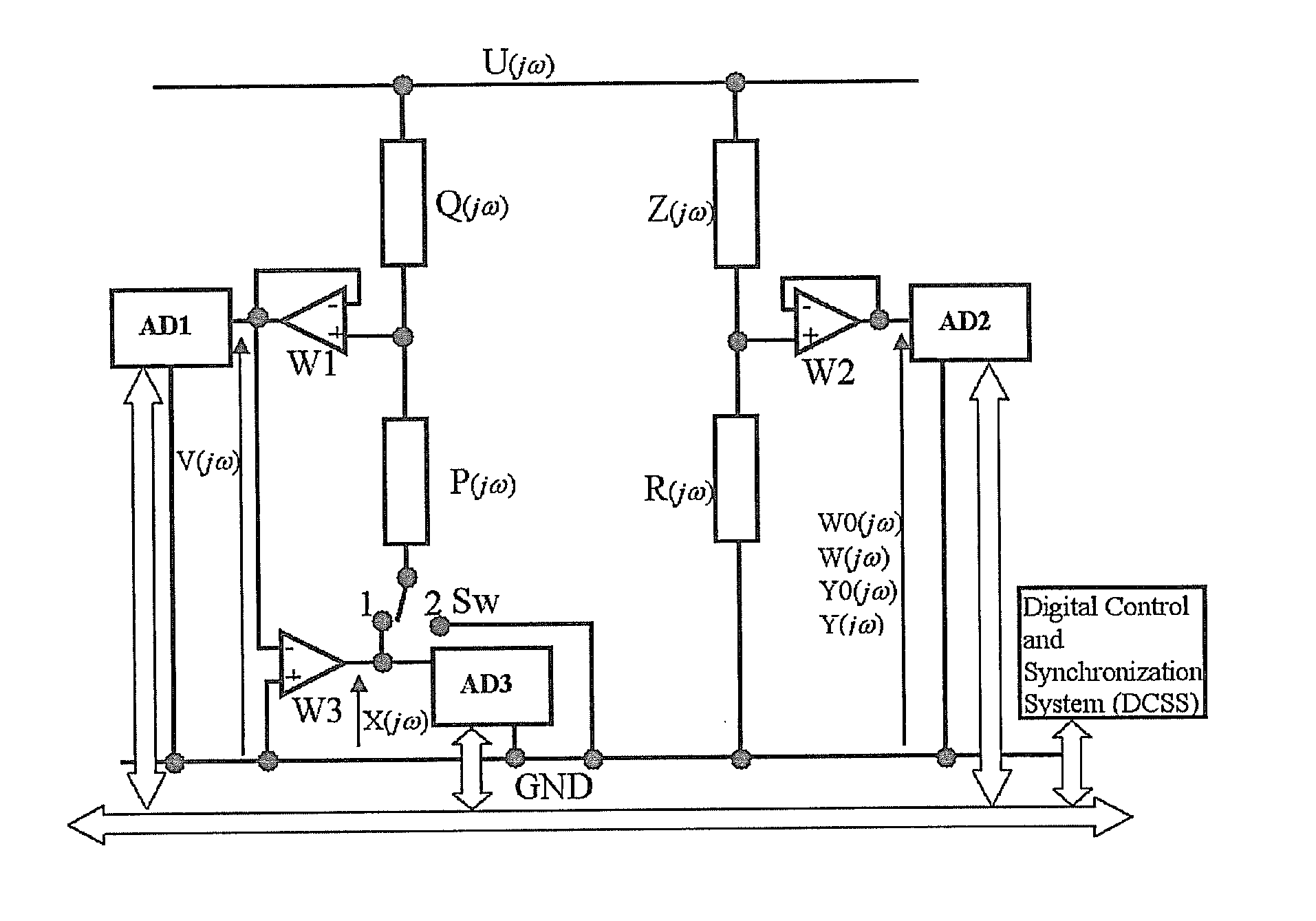
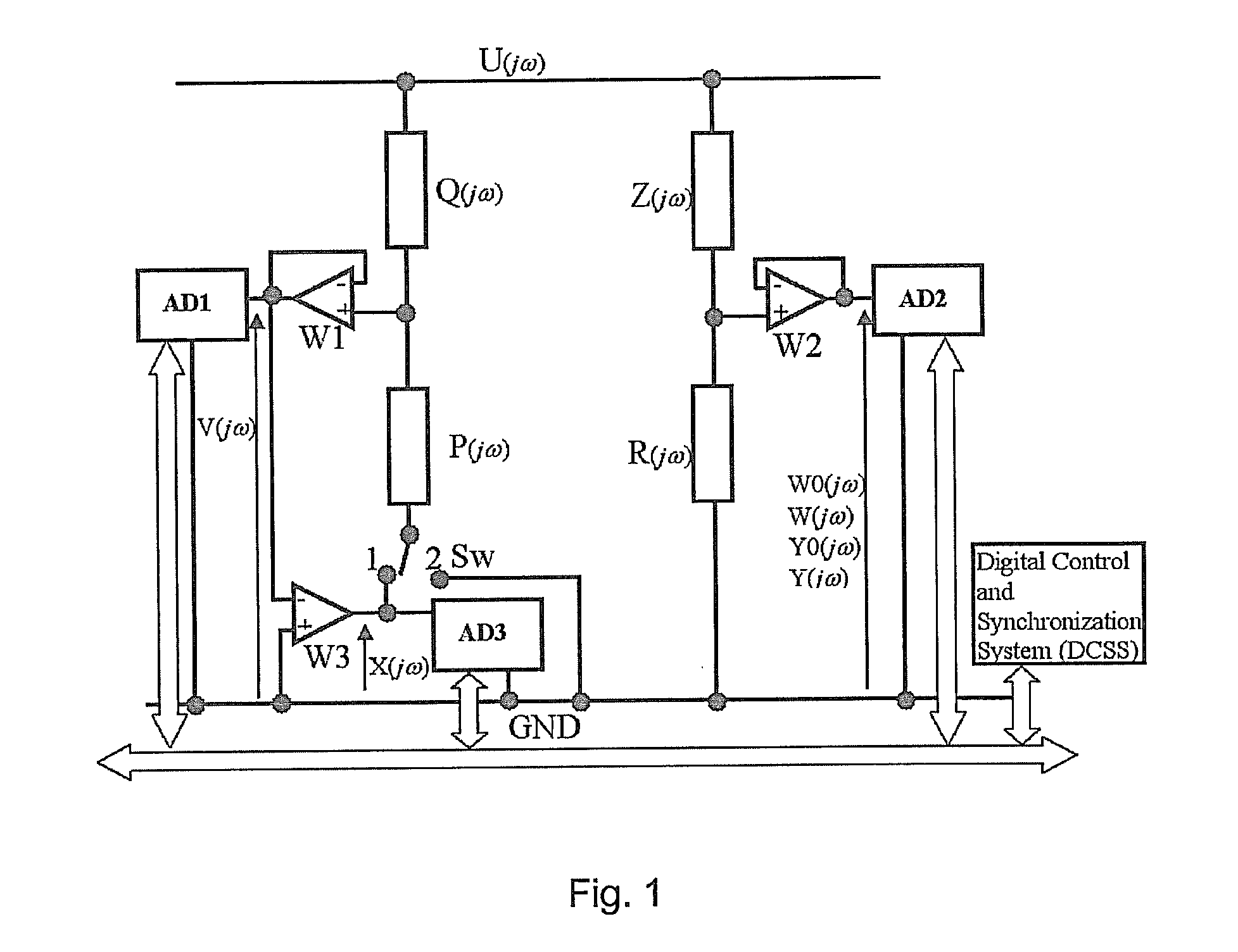
[0021]The adaptive voltage divider with corrected frequency characteristic for measuring high voltages according to the first example embodiment shown in FIG. 1. It comprises two branches—in the first branch impedance Q(jω) and impedance P(jω), which are connected to the first voltage follower whereof output is further connected to the first analog-to-digital converter whereas in its second branch it has series-connected impedance Z(jω) and impedance R(jω), connected to the second voltage follower whereof output is connected to second analog-to-digital converter. The adaptive voltage divider is furthermore provided with a switch Sw that allows to disconnect impedance P(jω) from the zero-potential terminal and connects it to the amplifier output whereof output is connected to the third analog-to-digital converter.

[0022]The adaptive voltage divider comprises: the impedance Q(jω) whereof one end is connected to the noninverting input of the first voltage follower W1 employ...

second embodiment

the Invention

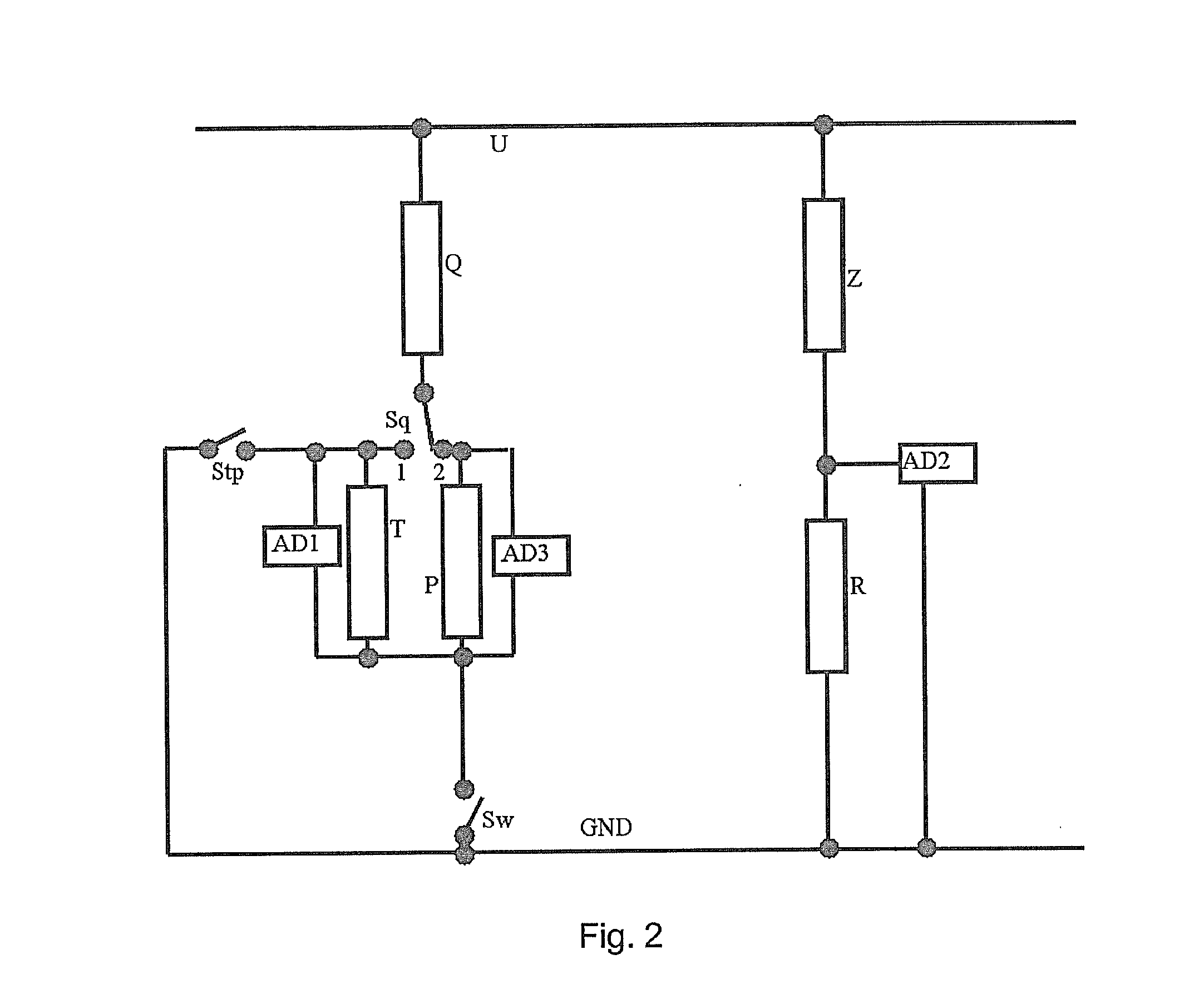
[0037]Configuration of the second example embodiment of the adaptive voltage divider according to the present invention is shown in FIG. 2.

[0038]For the sake of clarity of the description and figures, the impedances will be thereinafter denoted respectively by letters P, Q, etc. instead of P(jω), Q(jω), etc.

[0039]Impedance Q is connected in series through switch Sq, with a parallel connection of impedance T and analog-to-digital converter AD1 or with a parallel connection of impedance P and analog-to-digital converter AD2 whereas the common node of impedances Q and T is connected with switch Sw. Switch Stp provides connection of impedance Q to ground potential.

[0040]In the adaptive voltage divider the measurement signal is not passing through active elements, such as operational amplifiers, whose measuring properties would influence the measurement quality. The measurement signal passes only through passive elements whose dynamic properties are identified by the measuri...

third embodiment

the Invention

[0051]Configuration of the third example embodiment of the adaptive voltage divider according to the present invention is shown in FIG. 3.

[0052]This example embodiment is an extension of the example embodiment shown in FIG. 2 with the following modifications.

[0053]The value of impedance T1 should be approximate to the value of impedance T with a tolerance of several percent, similarly the value of impedance P1 should be approximate to the value of impedance P with a tolerance of several percent.

The Adaptive Voltage Divider Operation Phases:

Phase 1.

[0054]Switch Sa is set to position 1, switch Sq is set to position 2, switch Spt is open, switch Sw is in the closed position. The voltage measurements are performed by means of analog-to-digital converters AD2 and AD3. In this phase the relations between impedances Q and P, and Z and R are determined.

Phase 2.

[0055]Switch Sa is set to position 1, switch Sq is set to position 1, switch Spt is open, switch Sw is in the closed po...


PUM


Abstract

An adaptive voltage divider for measuring a high voltage between a ground terminal (GND) and a measurement terminal (U). It comprises a first branch comprising a first set of impedance elements (Z, R) forming a voltage divider circuit connected between the ground terminals (GND) and the measurement terminal (U) and a voltage meter (AD2) configured to measure voltage on one of the impedance elements (Z, R) of the first branch. Furthermore, it comprises a second branch comprising a second set of impedance elements (Q, P) connected between the ground terminal (GND) and the measurement terminal (U) and switchable between a plurality of configurations, wherein in at least one configuration the second set of impedance elements (Q, P) forms a voltage divider circuit, and voltage meters (AD1, AD3) configured to measure voltage on at least one of the impedance elements (Q, P) of the second branch. Moreover, a control circuit (DCSS) is configured to consecutively switch the configuration of the second branch between the plurality of configurations thereof, such that the relationships between the values of impedance elements (Z, R) of the first branch and the values of impedance elements (Q, P) of the second branch can be determined for consecutive configurations of the second branch as a function of the outputs of the voltage meters (AD1, AD2, AD3) and the total transmittance of the voltage divider can be determined at any instance as a function of the outputs of the voltage meters (AD1, AD2, AD3).

Description

TECHNICAL FIELD[0001]The present invention relates to an adaptive voltage divider with corrected frequency characteristic for measuring high voltages.BACKGROUND ART[0002]Classic voltage dividers: resistive, inductive or capacitive, have a number of drawbacks that will be discussed further below.[0003]Firstly, the voltage divider ratio varies in time due to components ageing or ambient conditions such as temperature, humidity or environment pollution. For instance, changes in air humidity cause changes in the leakage resistances shunting the divider impedances and thereby result in uncontrolled changes in the divider ratio. Similarly, external pollutants (dust, fat) shunting the divider elements give rise to uncontrolled changes in the divider ratio. Moreover, loading a divider with finite impedance also changes the divider ratio.[0004]Also dynamic properties of a voltage divider are subject to changes. Besides of resistance components, each voltage divider comprises parasitic reacta...

Claims


Application Information

Patent Timeline
IPC IPC(8): H03H7/24
CPCH03H7/24G01R15/06
Inventor NABIELEC, JERZY
Owner ACAD GORNICZO HUTNICZA IM STANISLAWA STASZICA
Learn More