Method for controlling a tool

a tool and position technology, applied in the field of method for controlling the position of the tool, can solve the problems of limiting the camera image of the nozzle, reducing the efficiency of the nozzle, and the size of the sheet metal plate from which the work piece is cut is typically too large to fully utilize the sheet metal plate in one method step, so as to reduce the complexity of the set up of the machine and the tool, facilitate precise positioning, and simple positioning

Inactive Publication Date: 2014-06-12
ACSYS LASERTECHN
View PDF17 Cites 28 Cited by
  • Summary
  • Abstract
  • Description
  • Claims
  • Application Information

AI Technical Summary

Benefits of technology

[0033]The describe method provides improvements over solutions that are known in the art in that the system significantly reduces set up complexity for machines and tools and facilitates exact positioning also for small work pie

Problems solved by technology

However, producing such auxiliary devices is rather time consuming and expensive for low volume production.
Thus, it is very problematic that the cutting gas nozzle restricts the camera image to a large extent due to its diameter of 1.5 mm at the most.
The standard formats of the sheet metal plates from which the work pieces are cut therefore are typically too large to fully utilize these sheet metal plates in one method step.
The left over sheet

Method used


Image

  • Method for controlling a tool
  • Method for controlling a tool
  • Method for controlling a tool

Examples


Embodiment Construction

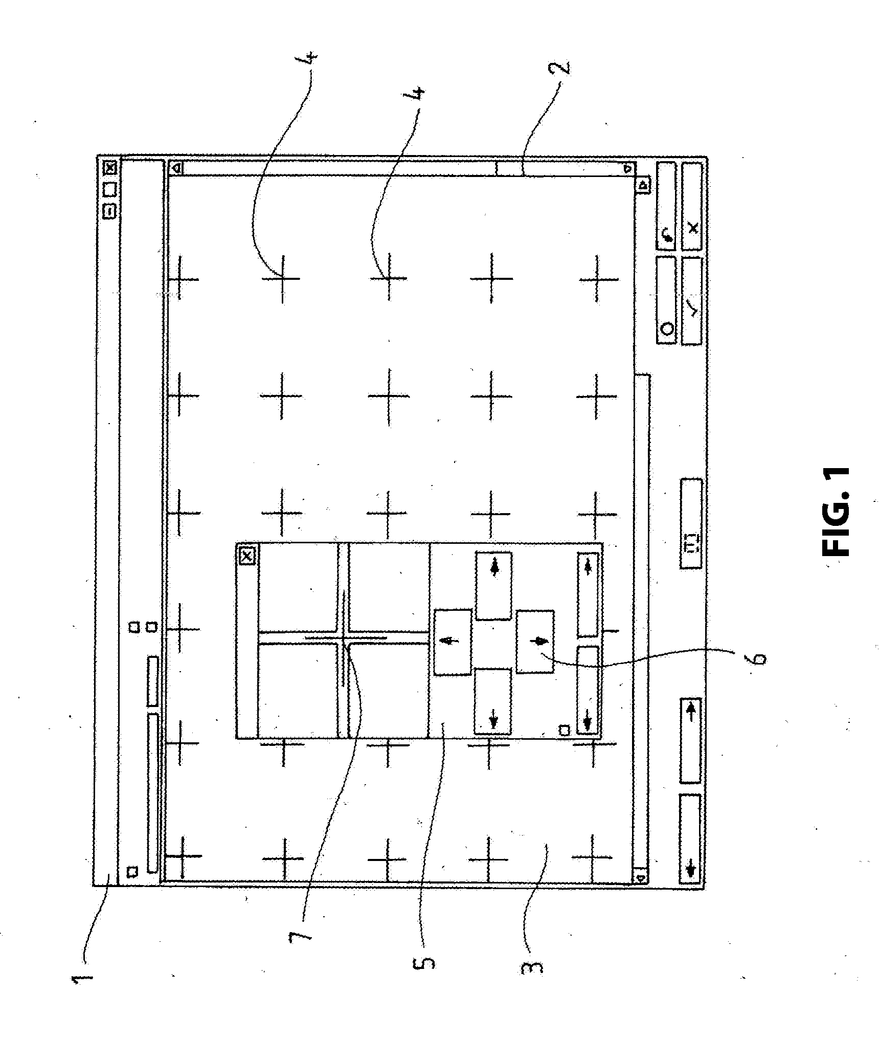
[0041]FIG. 1 illustrates a screen output of a control program 1 during correction of camera distortion, wherein a reference matrix 3 configured as evenly offset scaling crosses 4 is reproduced on a reference plate in a control window 2. A centering window 5 with super imposed target cross 7 is preferably positioned through cursor keys exactly on a selected reference point of the reference matrix 3, wherein the reference point is configured as a scaling cross 4. The skewing of the camera image is corrected in particular in the outer portion in that plural scaling crosses 4 of the reference matrix 3 are aligned one after the other with the target cross 7 of the camera image. This correction function corrects the skewing of the camera images for all subsequent images of work pieces.

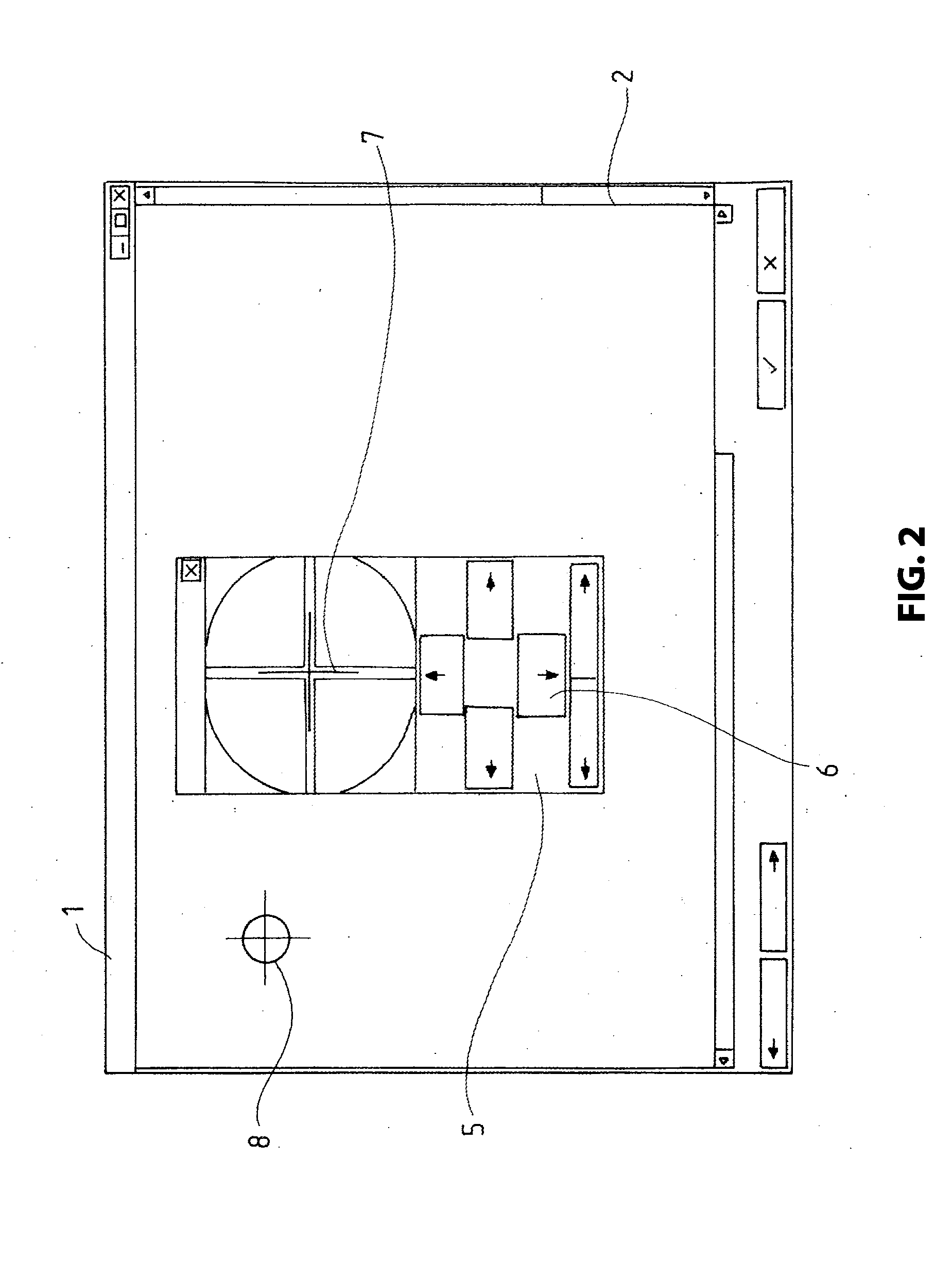
[0042]FIG. 2 illustrates the screen output of the control program 1 while centering the center point of the camera image, wherein the centering window 5 is aligned in the control window with the target cross...


PUM


Abstract

A method for controlling a tool, including the steps: providing a reference matrix including reference points and a centering matrix including centering points in a material processing plane; imaging the material processing plane through a camera as a camera image in a size of a camera image field; de-skewing the camera image of the material processing plane by aligning with the reference matrix; scaling a pixel size of the camera image through aligning with the reference matrix; centering the camera image through aligning with the centering points; projecting a processing contour onto the de-skewed and scaled camera image of a workpiece; and aligning the processing contour on the camera image of the work piece and starting the processing, wherein the processing of the work piece is performed though the tool along the processing contour.

Description

RELATED APPLICATIONS[0001]This patent application claims priority from and incorporates by reference German patent application DE 10 2012 106 156.4 filed on Jul. 9, 2013.FIELD OF THE INVENTION[0002]The invention relates to a method for controlling a position of a tool, wherein CAD data is projected as operating contours, in particular cutting geometries, onto a live camera image of a work piece to be processed.[0003]The method can be used in the fields of sheet metal processing, machining profiles and tubes, in proto type construction and in laser job production.BACKGROUND OF THE INVENTION[0004]A preferred application of the invention relates to materials processing through laser cutting which is described in the art in many aspects.[0005]A laser cutting device is known from for example from DE 20 2007 015 908 U1, wherein the laser cutting device collects the used protective gas, cleans it in a filter arrangement and resupplies it to the laser cutting process.[0006]A laser cutting m...

Claims


Application Information

Patent Timeline
IPC IPC(8): G06K9/32H04N7/18
CPCH04N7/18G06K9/3208G05B19/402G05B2219/35161G05B2219/35162
Inventor JEDYNAK, MIRKOKREISEL, CHRISTIANHEINRITZ, UWELIEBERS, RENE
Owner ACSYS LASERTECHN
Why Eureka
Try Eureka