Light emitting device and vehicle lamp

Active Publication Date: 2014-06-12
STANLEY ELECTRIC CO LTD
View PDF5 Cites 25 Cited by
  • Summary
  • Abstract
  • Description
  • Claims
  • Application Information

AI Technical Summary

Benefits of technology

[0033]Firstly, the light incident efficiency of light for use in local irradiation from the semiconductor light emitting element to be incident on the back surface of the light-transmitting member can be enhanced. This advantage results from the fact that the through hole is configured to increase in size from the front surface of the head portion to the back surface of the head portion, it is possible to prevent part of light pa

Problems solved by technology

In this case, there is a problem in that the adhesive may get burned due to the laser light e

Method used


Image

  • Light emitting device and vehicle lamp
  • Light emitting device and vehicle lamp
  • Light emitting device and vehicle lamp

Examples


Example

[0055]A description will now be made below to vehicle lamps of the presently disclosed subject matter with reference to the accompanying drawings in accordance with exemplary embodiments.

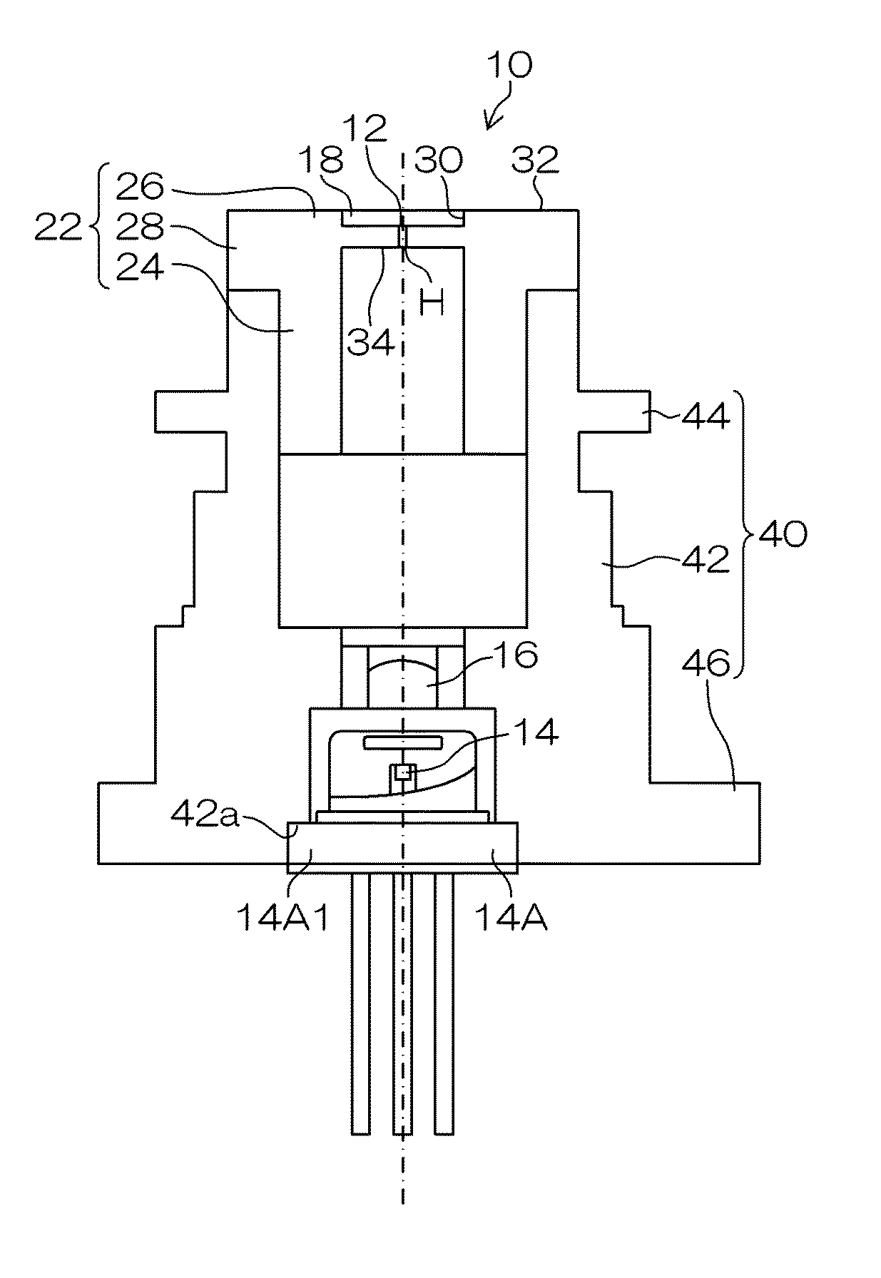
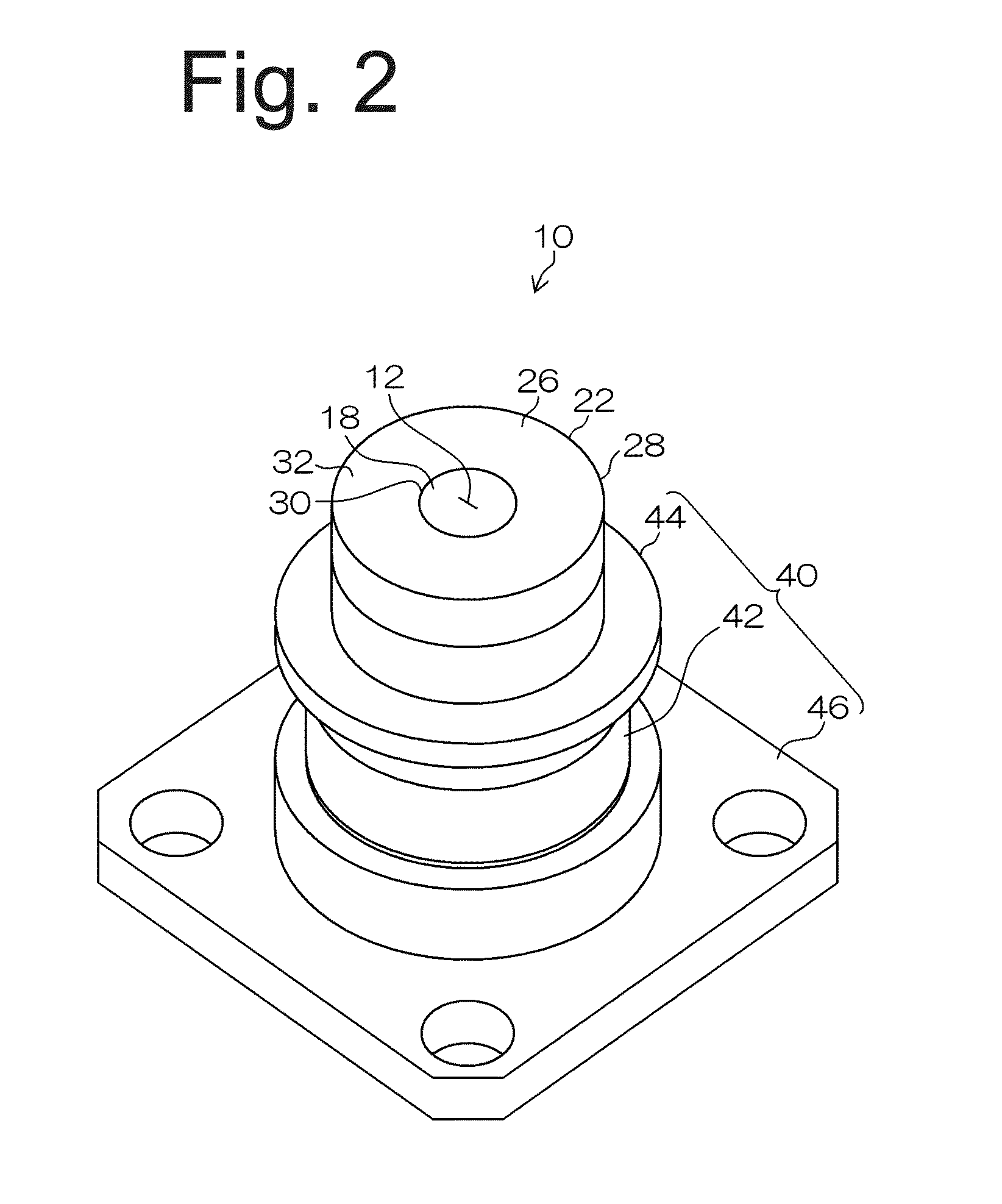
[0056]FIG. 2 is a perspective view of a light emitting device which is an embodiment made in accordance with principles of the presently disclosed subject matter. FIG. 3 is a longitudinal sectional view of the same. FIG. 4A is an enlarged partial sectional view near a through hole, and FIGS. 4B, 4C, 4D, and 4E each are an enlarged partial sectional view near a through hole as a modification.

[0057]As shown in FIGS. 2 to 4E, the light emitting device 10 can include a light-transmitting member 12, a semiconductor light emitting element 14, a condenser lens 16, a high reflectance member 18, a bonding material (adhesive) 20, and holders for holding such components, composed of a first holder 22 and a second holder 40.

[0058]The first holder 22 can be made of metal such as stainless steel. As shown in FIG....


PUM


Abstract

A light emitting device can include a head portion including a surface including a convex portion, a back surface on the opposite side, and a through hole penetrating a tip surface of the convex portion and the back surface; a light-transmitting member including a surface and a back surface on the opposite side, the back surface including a first recess to be fitted to the convex portion; an adhesive bonding part of the surface of the head portion around the convex portion to the back surface of the light-transmitting member while the convex portion is fitted to the first recess and the first recess covers the through hole; a semiconductor light emitting element that emits light passing through the through hole for irradiation of the light-transmitting member; and an optical system condensing the light from the semiconductor light emitting element and locally irradiates the light-transmitting member with the light.

Description

[0001]This application claims the priority benefit under 35 U.S.C. §119 of Japanese Patent Application No. 2012-267022 filed on Dec. 6, 2012, which is hereby incorporated in its entirety by reference.TECHNICAL FIELD[0002]The presently disclosed subject matter relates to a light emitting device, and more particularly to a light emitting device and a vehicle lamp having a structure in which a semiconductor light emitting element (for example, semiconductor laser light source) and a light-transmitting member are combined with each other.BACKGROUND ART[0003]A light emitting device having a structure that a semiconductor light emitting element (for example, semiconductor laser light source) and a light-transmitting member are combined with each other has heretofore been proposed (for example, see Japanese Patent Application Laid-Open No. 2010-165834).[0004]As shown in FIG. 1, a light emitting device 200 described in Japanese Patent Application Laid-Open No. 2010-165834 can include a semi...

Claims


Application Information

Patent Timeline
IPC IPC(8): F21S8/10
CPCF21Y2101/00F21K9/64F21Y2115/30F21S41/16F21V5/10F21V5/008F21S41/176H01S5/02212H01S5/02257H01S5/02H01S5/0087
Inventor HARADA, MITSUNORI
Owner STANLEY ELECTRIC CO LTD
Why Eureka
Try Eureka