Evaporative edge lithography of a liposomal drug microarray for cell migration assays
a liposomal drug and cell migration technology, applied in the field of liposomal microarrays, can solve the problem of limited current methods for analyzing cellular migration
- Summary
- Abstract
- Description
- Claims
- Application Information
AI Technical Summary
Benefits of technology
Problems solved by technology
Method used
Image
Examples
example 1
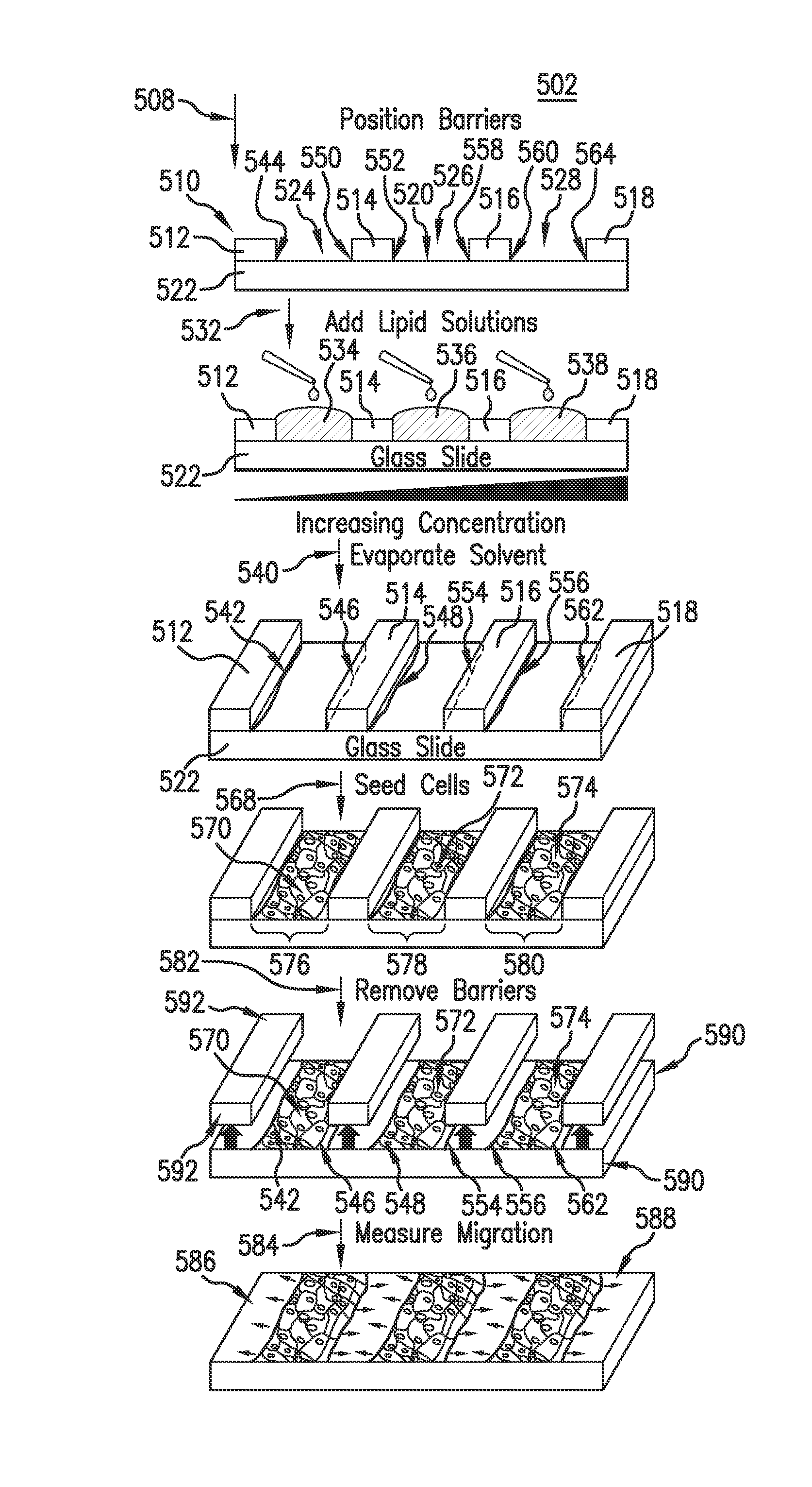
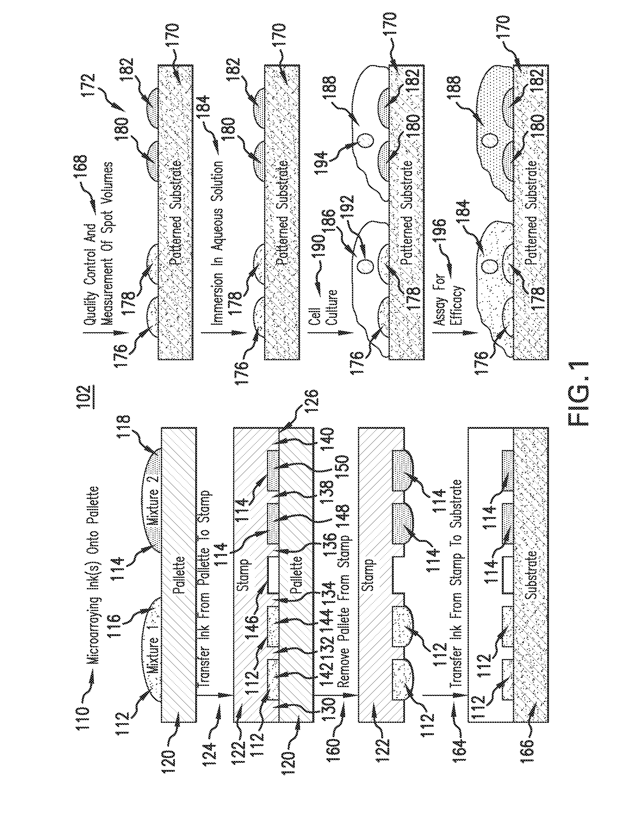
[0258]Lipid multilayer stamping techniques of the present invention, when combined with microarray technology should allow for the increase in throughput of printing. Coating of PDMS stamps has been done by dipping in a solution of the desired material or by the peeling method where the stamp is put on a drop of the material and peeled off.7 Using arrays of surface-supported liposomes for small molecule microarray screening is a very novel approach. FIGS. 12, 13, 13, 15, 16 and 17 show an illustration of liposomal structures in solution (state of the art) and on a surface using techniques of the present invention. These structures have similarities to solution based liposomes, which are well established lipid-based drug-delivery systems37, especially for drugs that may be may be insoluble in water6. Fundamental differences include: (1) the ability to test multiple different materials on cells within the same solution by means of the microarray concept and (2) the micro and nanostruc...
example 2
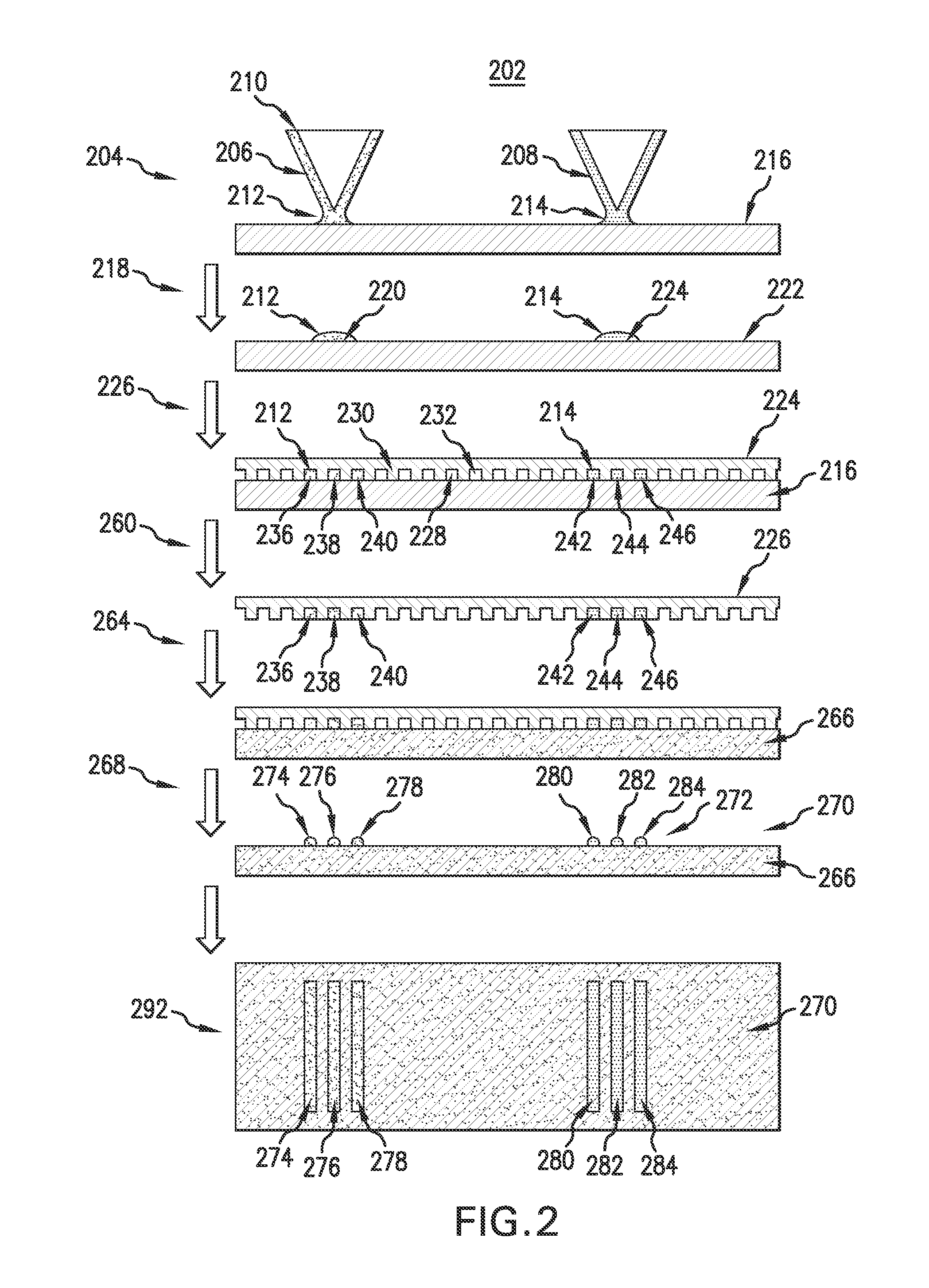
[0265]FIGS. 18, 19, 20, 21 and 22 represent the multiplexing capabilities of a microarraying process in combination with multilayer stamping according to one embodiment of the present invention. The microarrayer is capable of writing multiple inks onto the same substrate, as shown in panel 1812 of FIG. 18. The three different fluorophores used in the test shown in FIG. 18 were Marina Blue-DHPE (a blue fluorophore), carboxyfluorescein-PE (a green fluorophore) and rhodamine-pe (a red fluorophore), which were used in columns 1814, 1816 and 1818, respectively. With the washing protocol used, there was no cross contamination observed in this sample. Panel 1912 of FIG. 19 shows the ability of multilayer stamping according to one embodiment of the present invention to faithfully produce lipid dot patterns of DOTAP doped with different fluorophores. The fluorophores used in the test in FIG. 19 were Marina Blue-DHPE (column 1922), carboxyfluorescein-PE (column 1924) and rhodamine-PE (column ...
example 3
[0266]FIGS. 23, 24, 25, 26, 27, 28, 29 and 30 show how cells bind to and grow on patterned areas but not on the contiguous lipid multilayers (blobs). FIG. 23 is a 4× TRITC fluorescence micrograph of patterns of DOTAP stamped spots 2312, 2314, 2316 and 2318 printed onto glass 2342 using a 5 μm well stamp. FIG. 23 includes a region 2352 enclosed in white box. FIG. 24 presents the digital zoom of region 2352 of FIG. 23 showing greater detail of stamped spot 2316. FIG. 25 is 4× merged fluorescence micrograph of FITC and TRITC images of stamped spots 2312, 2314, 2316 and 2318. HeLa cells seeded on patterns adhere and grow. FIG. 25 includes a region 2532 enclosed in a white box. FIG. 26 is a 10× merged fluorescence micrograph of FITC and TRITC images of region 2532 of FIG. 25 show greater detail of stamped spot 2314. FIG. 27 is a 4×TRITC fluorescence micrograph of patterns of DOTAP stamped spots 2312, 2314, 2316 and 2318 printed directly onto glass using a microarrayer. FIG. 27 includes a...
PUM
| Property | Measurement | Unit |
|---|---|---|
| concentration | aaaaa | aaaaa |
| concentration | aaaaa | aaaaa |
| concentration | aaaaa | aaaaa |
Abstract
Description
Claims
Application Information
 - R&D
- Intellectual Property
- Life Sciences
- Materials
- Tech Scout
- Unparalleled Data Quality
- Higher Quality Content
- 60% Fewer Hallucinations
Browse by: Latest US Patents, China's latest patents, Technical Efficacy Thesaurus, Application Domain, Technology Topic, Popular Technical Reports.
© 2025 PatSnap. All rights reserved.Legal|Privacy policy|Modern Slavery Act Transparency Statement|Sitemap|About US| Contact US: help@patsnap.com


