
Lightning conductor system comprising a lightning conductor strip mounted in an offset manner

a technology of lightning conductors and conductor strips, which is applied in the direction of aircraft lighting protectors, connection to earth, aircraft indicators, etc., can solve the problems of insufficient solution, inability to completely satisfy, and inability to fully solve the problem of aircraft damage in flight, so as to reduce the radio-electrical failure of lightning conductor strips, reduce the effect of diffraction, and reduce the impact of radio-electrical failur

Active Publication Date: 2014-06-19
AIRBUS OPERATIONS (SAS)
View PDF2 Cites 3 Cited by
  • Summary
  • Abstract
  • Description
  • Claims
  • Application Information

AI Technical Summary

Benefits of technology

The invention simplifies the fixing of a lightning conductor strip by using intermediary parts that can be identical, reducing costs. The use of insulating inserts allows for a secure attachment of the conductor strip to the support structure and can also be used with a resin to further strengthen the connection. The conductor strip is designed in a cylindrical or circular section, which reduces the impact of radio-electrical failure and improves its performance. The invention also avoids constraints on fixing the conductor strip to the support structure, increasing assembly tolerances and simplifying the mounting process. Overall, the invention simplifies and improves the fixing of a lightning conductor strip while allowing for a more circular shape.

Problems solved by technology

Lightning can cause considerable damage to aircraft in flight, for example civil transport airplanes.
Although this second type of lightning conductor system 10 makes it possible to resolve any aerodynamics problem, this solution is not entirely satisfactory, particularly for the reasons exposed hereafter.
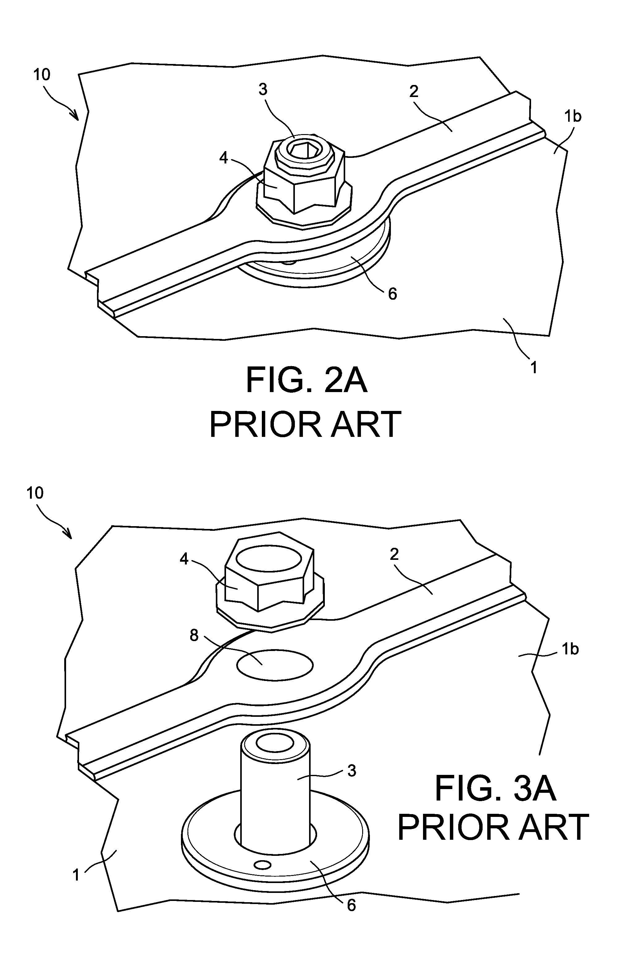
In fact, the conception of this lightning conductor system 10 of the prior art generally leads to a complexity in the machining and the assembly of the lightning conductor strips 2 and, as a result, an increase in costs.
In addition, as may be observed in FIG. 5A, the solution of the prior art may bring about difficulties of localisation during the fixing of the lightning conductor strips 2 on the radome 1.
Moreover, the lightning conductor strips 2 of this lightning conductor system 10 of the prior art may also exhibit a too important failure of radio-electric barrier vis-à-vis radar waves of the radome 1.

Method used


Image

  • Lightning conductor system comprising a lightning conductor strip mounted in an offset manner
  • Lightning conductor system comprising a lightning conductor strip mounted in an offset manner
  • Lightning conductor system comprising a lightning conductor strip mounted in an offset manner

Examples


Embodiment Construction

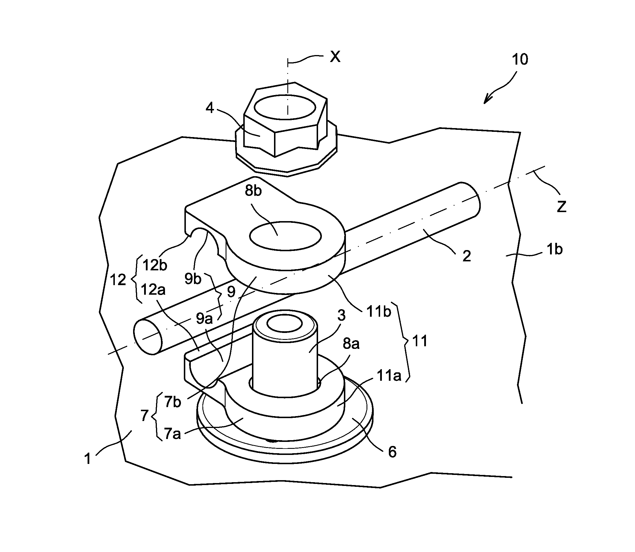
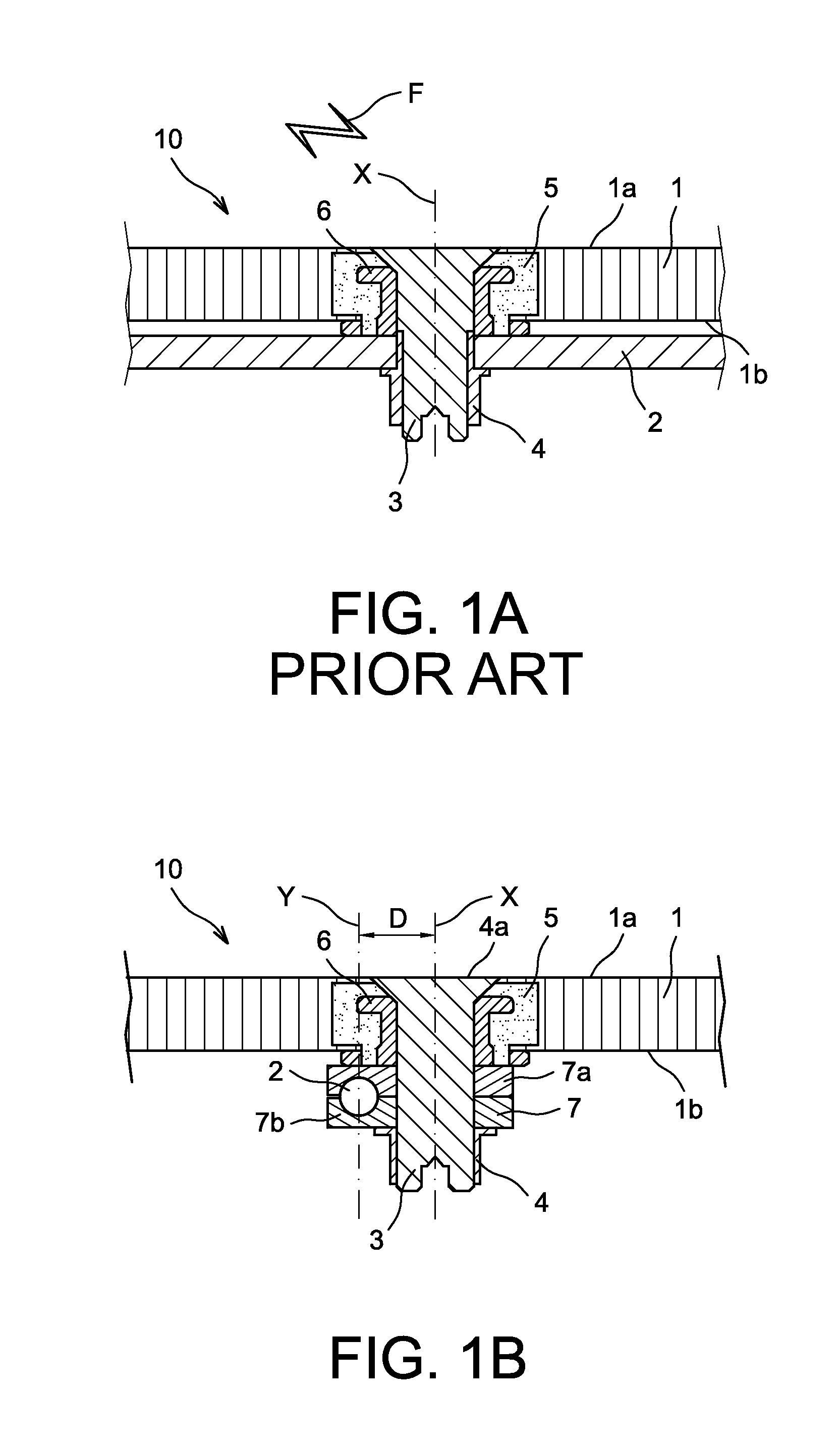
[0051]An example of implementation of the invention is described hereafter with reference to FIGS. 1B to 5B. FIGS. 1A to 5A, relative to the prior art, have been described previously.

[0052]An example of lightning conductor system 10 according to the invention has been represented, in section, in FIG. 1B.

[0053]The lightning conductor system 10 is provided to be used in relation with a support structure 1 having an external face 1a, intended to be subjected to a flow of air, and an internal face 1b, opposite to the external face 1a.

[0054]The support structure 1 may quite particularly be constituted of a radome 1 of an aircraft, particularly a nose cone radome of the aircraft. The radome 1 may for example comprise a “sandwich” composite structure comprising two walls and a honeycombed central core.

[0055]FIGS. 2B and 3B are perspective views of the lightning conductor system 10 of FIG. 1B, respectively in an assembled configuration and in an exploded configuration.

[0056]FIG. 4B represe...


PUM


Abstract

A lightning conductor system for a support structure having an external face intended to be subjected to a flow of air and an internal face opposite the external face, the lightning conductor system comprising an electrically conducting lightning conductor strip, intended to be placed on the side of the internal face of the support structure while being connected to ground, and means of fixing the lightning conductor strip to the support structure, the fixing means comprising fixing studs intended to be inserted into orifices formed in the support structure, said fixing studs being in electrical contact with the lightning conductor strip. The lightning conductor system includes the lightning conductor strip being mounted in an offset manner with respect to the main axes of the fixing studs.

Description

CROSS-REFERENCES TO RELATED APPLICATIONS[0001]This application claims the benefit of the French patent application No. 12 62124 filed on Dec. 17, 2012, the entire disclosures of which are incorporated herein by way of reference.TECHNICAL FIELD[0002]The present invention relates to the field of lightning conductor systems. More specifically, it relates to a lightning conductor system for a support structure, a support structure and a radome comprising such a lightning conductor system, as well as an aircraft comprising a radome equipped with said lightning conductor system.[0003]The invention mainly finds application in the field of aeronautics, particularly for the equipment of aircraft radomes.BACKGROUND OF THE INVENTION[0004]Lightning can cause considerable damage to aircraft in flight, for example civil transport airplanes. In order to protect these aircraft and to minimize the damage that can be caused by lightning, it is known to place lightning conductor protection strips on t...

Claims


Application Information

Patent Timeline
Patent Type & Authority Applications(United States)
IPC IPC(8): B64D45/02
CPCB64D45/02H02G3/32H02G13/40
Inventor MARTY, JEAN-CLAUDEFOURNIE, JACQUESBERNUS, CHRISTOPHEDUPAS, THONY
Owner AIRBUS OPERATIONS (SAS)
Learn More