
Computed radiography (CR) system

a computed radiography and cassette technology, applied in the field of computed radiography (cr) systems, can solve the problems of limited clinical acceptance, dr systems are much more expensive than cr, and the replacement cost of a worn out or broken dr detector can be ten to one hundred times more expensive than a cr cassette replacement, so as to reduce “swank noise” and reduce depth-dependent optical gain. , the effect of uniform optical spectrum distribution

Active Publication Date: 2014-06-19
DIGIRAY
View PDF3 Cites 1 Cited by
  • Summary
  • Abstract
  • Description
  • Claims
  • Application Information

AI Technical Summary

Benefits of technology

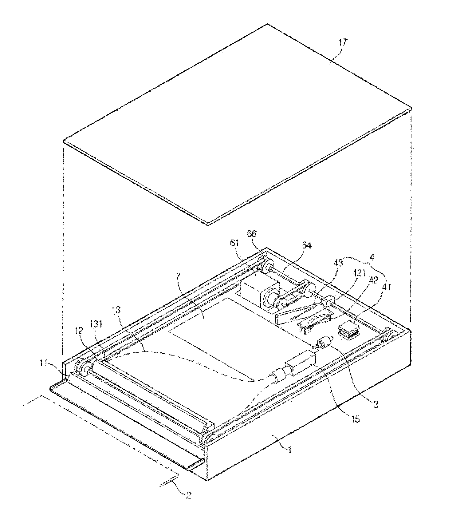
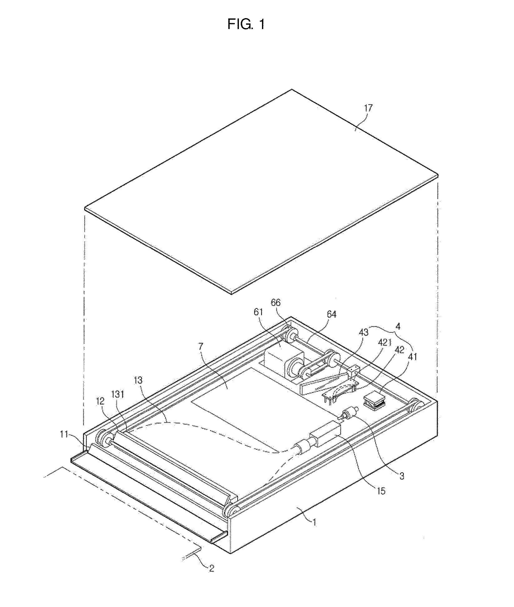
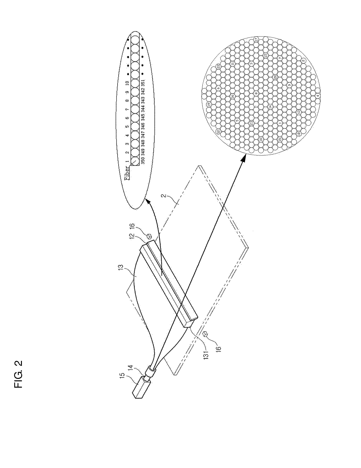
The present invention is a computed radiography (CR) system that has several advantages. The system has a uniform optical spectrum distribution which reduces high-frequency pattern problem. It also has low depth-dependent variations in optical gain, which reduces "Swank noise." This means that the system can detect electronic signals accurately and without being affected by unwanted noise. The CR system based on the plurality of optical fibers arranged in order, along zigzag pattern, provides image quality equal to or better than dry plate (DR) for high-resolution application of mammography. It is affordable and easy to use. Overall, the present invention solves the image quality limitations of traditional CR systems.

Problems solved by technology

DR systems, however, are much more expensive than CR, which has limited their clinical acceptance.
Furthermore, the replacement cost for a worn out or broken DR detector can be ten to one hundred times more expensive than replacing a CR cassette.
The image quality performance of CR has been limited in the past by two factors: (1) Because of limitations in screen conversion gain, collection efficiency, and detection efficiency, in a CR system that is not optimally designed, the number of detected electrons per absorbed x-ray (“gain”) can become low enough to become a secondary quantum sink, (2) CR systems have been observed to have rather high gain fluctuation noise, or “Swank noise”, compared to high quality SF or DR systems, where “the Swank noise” can degrade DQE performance and is quantified by the optical Swank factor, which is induced by depth-dependent variations in optical gain.

Method used


Image

  • Computed radiography (CR) system
  • Computed radiography (CR) system
  • Computed radiography (CR) system

Examples


experimental example

[0049]X-Ray Imaging Performance

[0050]In order to compare X-ray Imaging Performance of a computed radiography (CR) system according to an exemplary embodiment of the present invention with the same of the conventional CR system, Detective Quantum Efficiency (DQE) will be considered.

[0051]The DQE can be used to identify important factors to measure and to calculate their effect on the signal-to-noise performance of the CR system. We assume a scanning laser spot readout.

[0052]The DQE is a measure of the dose efficiency of the detector. It can be calculated using the equation:

DQE(f)=K2MTF2(f)MPS(f)Q

[0053]where f is the spatial frequency, K is the slope of the characteristic curve, and Q is the x-ray photon fluency incident on the light detector 15, and Noise power spectrum (NPS) characterizes the amount of noise and its texture, will be measured using standard techniques.

[0054]The shape of the NPS is important in determining the presence of secondary quantum noise. Secondary quantum noi...


PUM


Abstract

An exemplary embodiment of the present invention provides a computed radiography system, comprising a stimulating light source, a imaging plate (IP) positioned such that the stimulating light impinges the IP perpendicularly thereto producing photostimulated luminescence light (PLL) having a wave length different from said stimulating light source, a light collector having a bundle of optical fibers for collecting and transferring PLL emitted from the IP, the bundle providing with a liner end proximate to the IP and a two-dimensional end far away from the IP in which a plurality of optical fibers are arranged according to a constant rule, an optical filter in communication with said light collector for blocking stimulating light waves and passing PLL therethrough, a light detector for receiving PLL from the two-dimensional end of the bundle of the light collector.

Description

CROSS-REFERENCE TO RELATED APPLICATION[0001]This application claims priority to and the benefit of Korean Patent Application No. 10-2012-0147743 filed in the Korean Intellectual Property Office on Dec. 17, 2012, the entire contents of which are incorporated herein by reference.BACKGROUND OF THE INVENTION[0002](a) Field of the Invention[0003]This invention relates to a computed radiography (CR) system which employs a light collector such as a bundle of optical fibers. More particularly, this invention relates to a computed radiography (CR) system employing a bundle of optical fibers for collecting and transferring luminescence light, having a linear end and a two-dimensional end in which a plurality of optical fibers are sequentially arranged according to an input order of light.[0004](b) Description of the Related Art[0005]In recent years, computed radiography (CR) systems have been successful in replacing analog screen / film (SF) in many clinical settings. Such CR systems use photos...

Claims


Application Information

Patent Timeline
Patent Type & Authority Applications(United States)
IPC IPC(8): G01T1/29
CPCG01T1/2012G01N23/046
Inventor LEE, SUNG WOONKIM
Owner DIGIRAY
Learn More