Sheet transporting apparatus and image forming system

Active Publication Date: 2014-06-19
BROTHER KOGYO KK
View PDF2 Cites 2 Cited by
  • Summary
  • Abstract
  • Description
  • Claims
  • Application Information

AI Technical Summary

Benefits of technology

[0024]In the case of the transport mechanism as described above, the pressure, which is allowed to act on the group of sheets in accordance with the reaction described above, is raised, when the input current to be inputted into the motor is excessively larger than the adequate or proper value corresponding to the load when the sheet is taken out of the tray. Fu

Problems solved by technology

However, when the curvature is increased, the load fluctuation acting on the motor is increased when the printing paper is transported.
The load fluctuation tends to be caused especially when the printing paper as the transport object is thick.
Therefore, if any sudden decrease in the load arises, then the input current to be inputted into the motor is excessively lowered, and there is such a possibility that the output of the motor may be below the reaction force (for example, the k

Method used


Image

  • Sheet transporting apparatus and image forming system
  • Sheet transporting apparatus and image forming system
  • Sheet transporting apparatus and image forming system

Examples


Example

First Embodiment

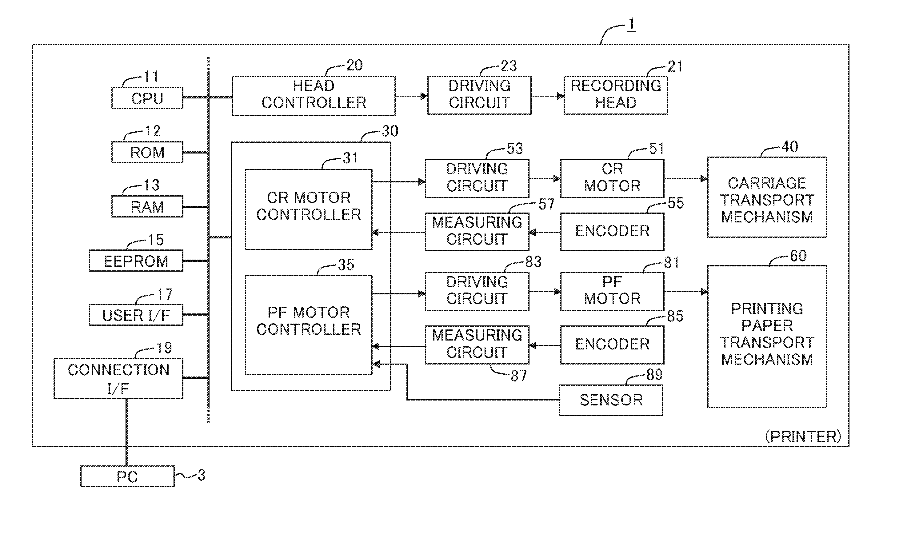
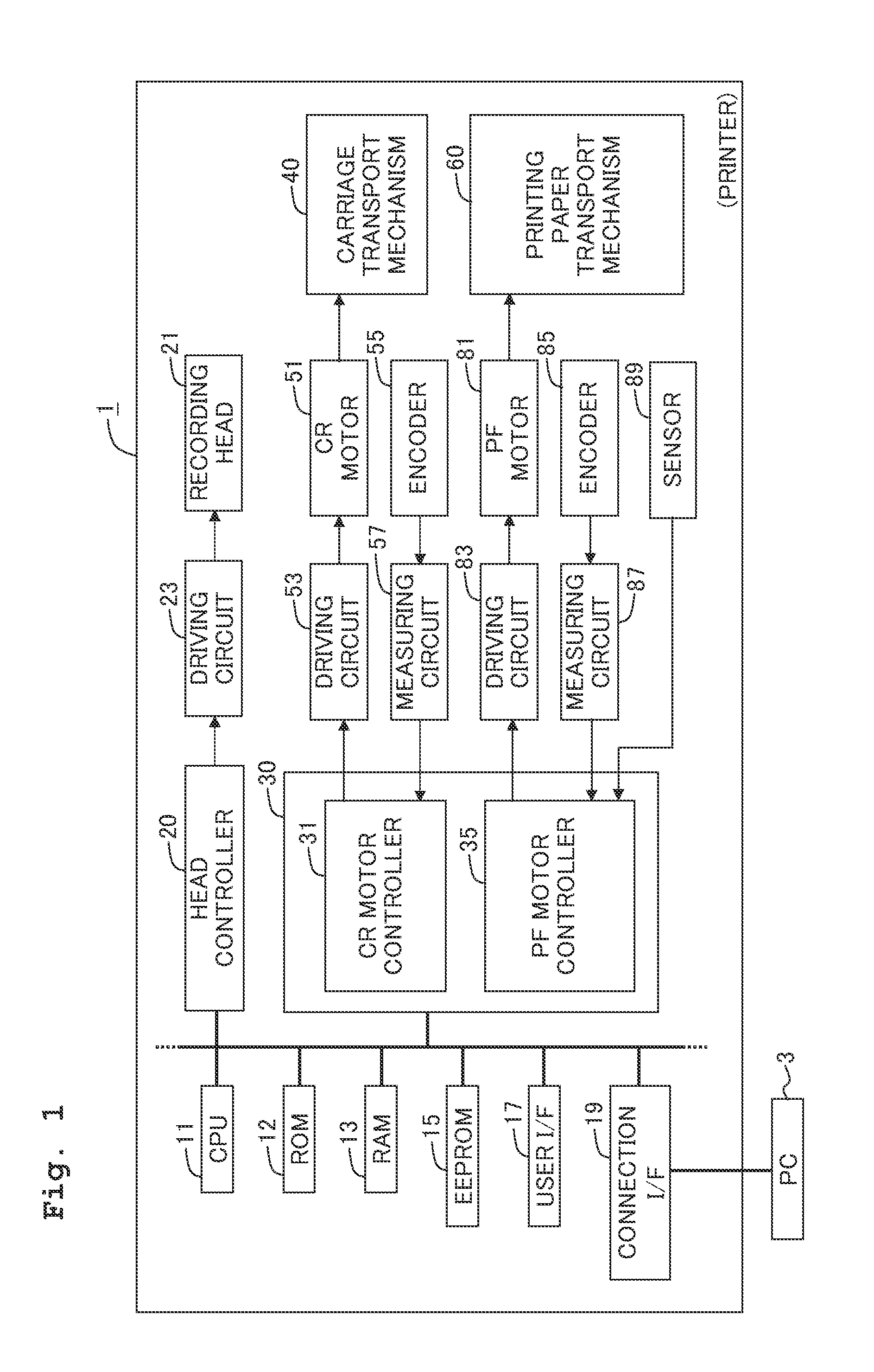
[0041]A printer 1 of this embodiment is ink-jet printer. The ink-jet printer can transport paper Q and can discharge ink liquid droplets onto the printing paper Q to form an image. The printer 1 has CPU 11, ROM 12, RAM 13, EEPROM 15, a user interface 17, a connection interface 19, a head controller 20, and a motor controller 30.

[0042]The printer 1 further has a recording head 21 and a driving circuit 23 as the construction for forming the image on the printing paper Q. Further, the printer 1 has a carriage transport mechanism 40, a CR motor 51, a driving circuit 53, a linear encoder 55, and a measuring circuit 57 as the construction for transporting the recording head 21 in the main scanning direction. The printer 1 can observe the displacement of a carriage 41 which carries the recording head 21, by means of the linear encoder 55 and the measuring circuit 57.

[0043]Other than the above, the printer 1 has a printing paper transport mechanism 60, a PF motor 81, a drivi...

Example

Second Embodiment

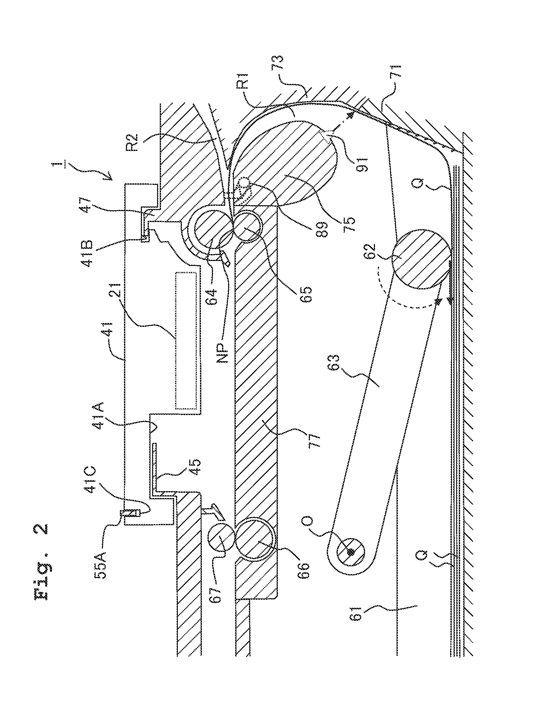
[0159]Next, a printer 1 of a second embodiment will be explained. However, the printer 1 of the second embodiment is constructed in the same manner as the printer 1 of the first embodiment except that a sensor 91 (see FIG. 2) is provided at an upstream side end portion of the curved area R1 and the contents of the paper feed control process are different from those of the first embodiment. Therefore, the construction, which is different from that of the first embodiment, will be selectively explained below as the explanation about the printer 1 of the second embodiment.

[0160]In the first embodiment, taking the opportunity of the detection of the printing paper forward end by the sensor 89 as the so-called registration sensor, the control on the PF motor 81 is switched from the closed loop control to the open loop control. The sudden load fluctuation, which is the reason to perform the switching of the control as described above, is caused while taking the opportunit...

Example

Third Embodiment

[0172]Next, a printer 1 of a third embodiment will be explained. However, the printer 1 of the third embodiment is constructed in the same manner as the printer 1 of the embodiment described above except that the control on the PF motor 81 is switched from the closed loop control to the open loop control irrelevant to the output signals from the sensors 89, 91. Therefore, the construction, which is different from that of the embodiment described above, will be selectively explained below as the explanation about the printer 1 of the third embodiment.

[0173]The PF motor controller 35 of the third embodiment executes a paper feed control process shown in FIG. 11 in place of the paper feed control processes shown in FIGS. 5 and 10. When the paper feed control process is started, the PF motor controller 35 executes the closed loop control on the PF motor 81 in the same manner as in Step S210 of the first embodiment. Accordingly, the paper feed roller 62 is positively rota...


PUM


Abstract

A sheet transporting apparatus is provided, including a transport mechanism provided with a roller, a motor, a controller, and a measuring input unit, wherein a transport route has a curved area for inverting the sheet, and the controller is constructed such that the control on the motor is executed by a closed loop control system by using a measured value of an control output at an initial stage of the transport of a sheet from a tray, and the control on the motor is switched from the control performed by the closed loop control system to control performed by an open loop control system on condition that a preset phenomenon arises after the sheet is taken out of the tray.

Description

CROSS REFERENCE TO RELATED APPLICATION[0001]The present invention claims priority from Japanese Patent Application No. 2012-273643, filed on Dec. 14, 2012, the disclosure of which is incorporated herein by reference in its entirety.BACKGROUND OF THE INVENTION[0002]1. Field of the Invention[0003]The present invention relates to a sheet transporting apparatus and an image forming system.[0004]2. Description of the Related Art[0005]An image forming system that includes a paper feeding tray, a feed roller and transporting roller is known. The feed roller feeds the printing paper accommodated in the paper feeding tray. And the feed roller feeds the printing paper toward the transporting roller which is disposed on the downstream of a transport path. These rollers are driven by a motor. According to the image forming system of the type as described above, the printing paper, which is fed from the paper feeding tray, is transported to an image forming area disposed on the further downstrea...

Claims


Application Information

Patent Timeline
IPC IPC(8): B41J13/00
CPCB65H2511/414B65H2557/26B65H2557/264B65H2801/39B65H3/0684B65H9/008B65H7/06B65H2511/24B65H2515/70B65H2220/02B65H2220/01B41J13/0009B65H5/062B65H7/08B65H2801/12
Inventor SAMOTO, KENJIHORADE, KENTANOZAKI, MITSUHIROAOKI, HIROTAKA
Owner BROTHER KOGYO KK
Why Eureka
Try Eureka