
Image forming apparatus that suppresses occurrence of color shift in images and method of controlling the same

a technology of image forming apparatus and color shift, which is applied in the direction of electrographic process apparatus, printing, instruments, etc., can solve the problems of image color shift, difficult to control the surface speed of the photosensitive drum difficult to control the surface speed of the intermediate transfer member to a constant speed, so as to suppress the occurrence of color shift

Active Publication Date: 2014-06-19
CANON KK
View PDF2 Cites 5 Cited by
  • Summary
  • Abstract
  • Description
  • Claims
  • Application Information

AI Technical Summary

Benefits of technology

The present invention provides an image forming apparatus and method that prevents color shifting in images transferred from multiple image bearing members to an intermediate transfer member.

Problems solved by technology

Therefore, if the timing of starting to form an electrostatic latent image on each photosensitive drum is not adjusted to be uniform between the colors, the transferred images formed on the intermediate transfer member are displaced between the colors, causing image color shift, which is positional displacement between images of respective colors formed on a recording sheet.
In the above-mentioned speed feedback control, the rotational speed of the drum shaft is detected, but it is difficult to control the surface speed of the photosensitive drum to a constant speed due to off-centering, a mounting error and the like of each of the photosensitive drum, the motor, and drive gears.
Similarly, in the intermediate transfer member as well, it is difficult to control the surface speed of the intermediate transfer member to a constant speed due to off-centering, a mounting error, and the like, of each of the motor and drive gears for driving the intermediate transfer member.
Further, causes of the image defects include mutual interference caused by friction between the surface of the photosensitive drum and the transfer surface of the intermediate transfer member.
As another cause, there may be mentioned an occurrence of an unplanned change in load on the intermediate transfer member during secondary transfer of a toner image carried on the intermediate transfer member onto a recording sheet, especially when the recording sheet is thick paper.
This causes a high-frequency speed variation, and this speed variation causes positional displacement in the primary transfer.
As described above, there are various causes of the image defects, and it is very difficult to eliminate all of the causes.
However, in the method of shifting the timing of starting to form an electrostatic latent image between the photosensitive drums by a time period required for an image already transferred onto the intermediate transfer member to be conveyed from one photosensitive drum to the next one, so as to prevent occurrence of image color shift, there arises a problem that a time period required for a latent image and its resulting image formed by development on each photosensitive drum, to advance from an exposure light irradiated position to a primary transfer position, and a time period required for a transferred image on the intermediate transfer member to be conveyed from one photosensitive drum to another are made different by an extent corresponding to variation in the respective speeds of the photosensitive drum and the intermediate transfer member.

Method used


Image

  • Image forming apparatus that suppresses occurrence of color shift in images and method of controlling the same
  • Image forming apparatus that suppresses occurrence of color shift in images and method of controlling the same
  • Image forming apparatus that suppresses occurrence of color shift in images and method of controlling the same

Examples


first embodiment

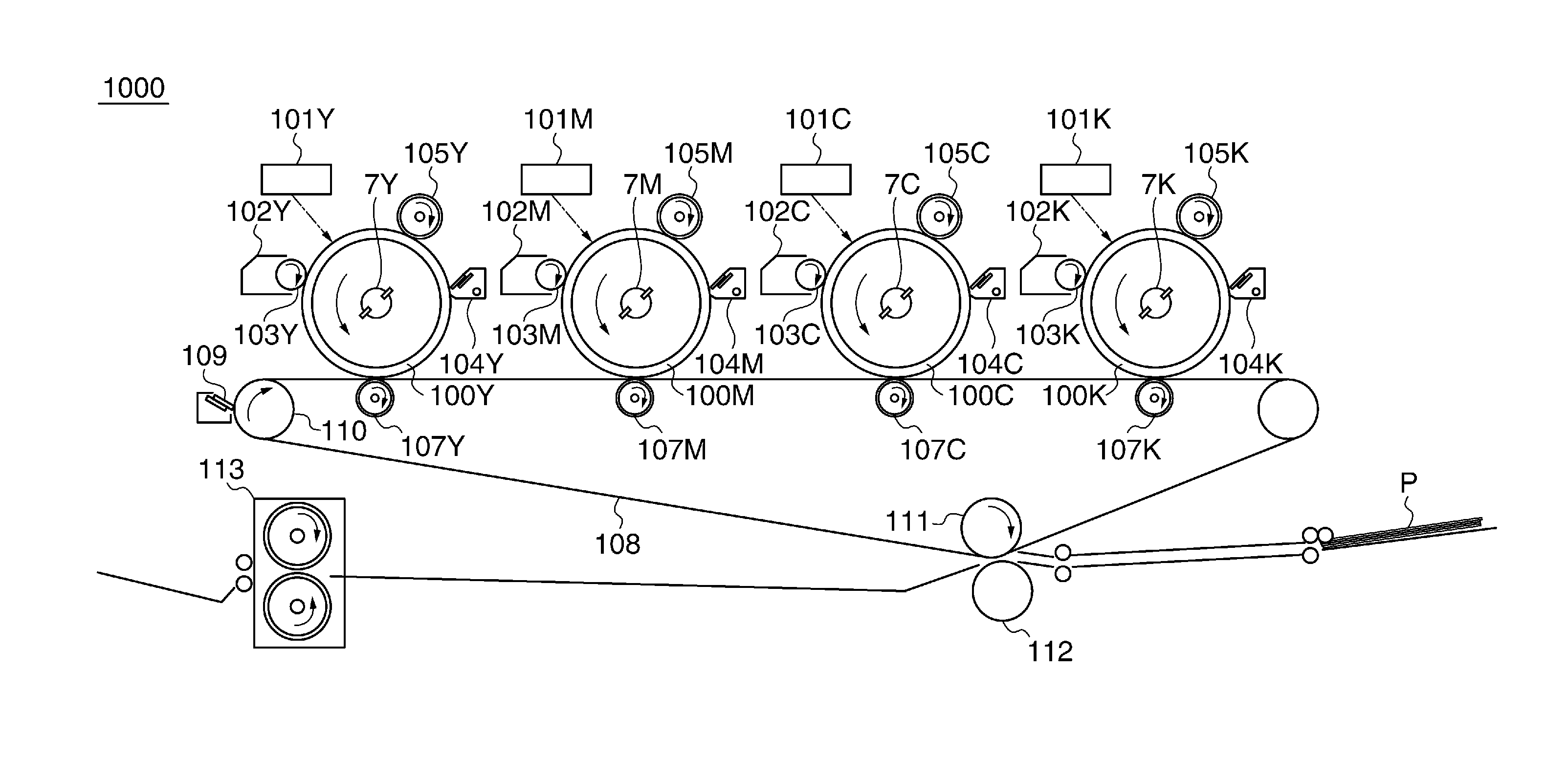
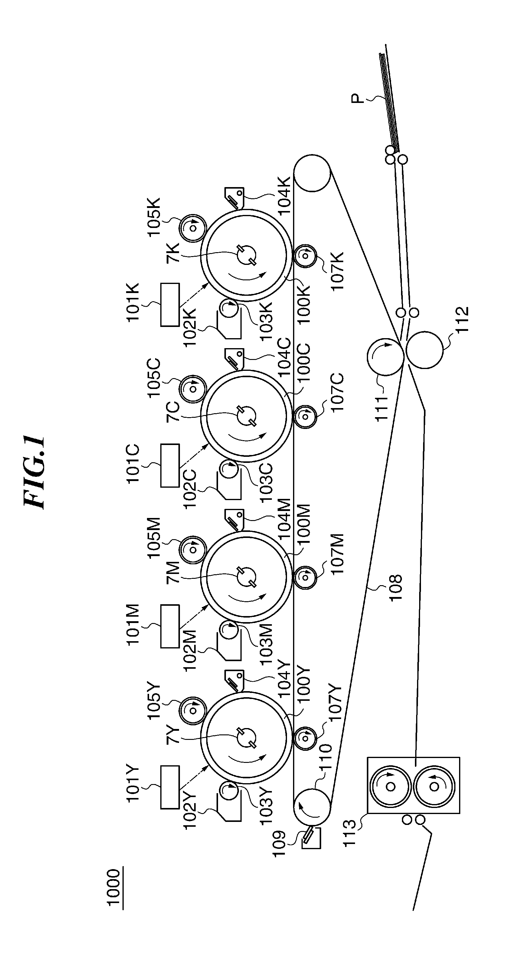
[0054]FIG. 1 is a schematic diagram of an image forming apparatus 1000 according to the present invention.

[0055]Referring toFIG. 1, the image forming apparatus 1000 is capable of forming images of the four colors of yellow (hereinafter referred to as “Y”), magenta (hereinafter referred to as “M”), cyan (hereinafter referred to as “C”), and black (hereinafter referred to as “K”). In FIG. 1, although component elements for the respective colors of Y, M, C, and K are denoted by reference numerals including Y, M, C, and K, when the component elements are not specifically distinguished from each other, Y, M, C, and K are omitted.

[0056]When the image forming apparatus 1000 receives an instruction for forming an image on a recording sheet P from a host CPU, referred to hereinafter, there start to rotate a plurality of photosensitive drums 100 (image bearing members), an intermediate transfer member (intermediate transfer belt; abbreviated to “ITB” in the drawings) 108, electrostatic chargi...

second embodiment

[0289]FIG. 26 is a flowchart of a print process executed by the CPU 13 of the control unit 2 of the image forming apparatus according to the

[0290]Referring to FIG. 26, when the controller 60 receives a print operation command, the controller 60 outputs a command signal for starting various process control to the host CPU 1. At the same time, image data is input from the controller 60 to the control unit 2 (step S401).

[0291]The CPU 13 divides the image data into information items of the respective colors Y, M, C, and K for controlling the exposure devices 101 (step S402).

[0292]When the CPU 13 receives an exposure start signal from the host CPU 1 (YES to a step S403), the CPU 13 outputs a CLK signal and a PWM signal to the exposure device 101Y as control signals (step S404). The subsequent sub scanning exposure timing is determined according to the sub scanning exposure timing interval Δt.

[0293]Then, whenever a pulse edge of the signal from the drum rotary encoder 7Y is detected, the ...

third embodiment

[0324]FIG. 27 is a flowchart of a print process executed by the CPU 13 of the control unit 2 of the image forming apparatus according to the

[0325]Referring to FIG. 27, when the controller 60 receives a print operation command, the controller 60 outputs a command signal for starting various process controls to the host CPU 1. At the same time, image data is input from the controller 60 to the control unit 2 (step S501).

[0326]The CPU 13 divides the image data into information items of the respective colors Y, M, C, and K for controlling the exposure devices 101 (step S502).

[0327]When the CPU 13 receives an exposure start signal from the host CPU 1 (YES to a step S503), the CPU 13 outputs a CLK signal and a PWM signal to the exposure device 101Y as control signals (step S504). The subsequent sub scanning exposure timing is determined according to the sub scanning exposure timing interval Δt.

[0328]Then, whenever a pulse edge of the signal from the drum rotary encoder 7Y is detected, the...


PUM


Abstract

An image forming apparatus that suppresses occurrence of color shift in images transferred from image bearing members onto an intermediate transfer member. A surface of each of a first photosensitive drum and second photosensitive drums is charged. An exposure device, provided for each photosensitive drum, forms an electrostatic latent image by exposing an associated one of the charged photosensitive drums. A developing device, provided for each photosensitive drum, develops the electrostatic latent image with toner. An intermediate transfer belt friction-drives the photosensitive drums for rotation and has the developed images transferred thereon. Timing for exposing the second photosensitive drums is controlled based on a first surface distance from an exposure light irradiated position to a primary transfer position of the first photosensitive drum, and a second surface distance from an exposure light irradiated position of each second photosensitive drum to a primary transfer position thereof.

Description

BACKGROUND OF THE INVENTION[0001]1. Field of the Invention[0002]The present invention relates to an electrophotographic image forming apparatus that suppresses occurrence of color shift in images and a method of controlling the same.[0003]2. Description of the Related Art[0004]In a tandem-type electrophotographic image forming apparatus including photosensitive drums, transfer positions at which images are primarily transferred from the respective photosensitive drums onto an intermediate transfer member are different between the photosensitive drums. Therefore, if the timing of starting to form an electrostatic latent image on each photosensitive drum is not adjusted to be uniform between the colors, the transferred images formed on the intermediate transfer member are displaced between the colors, causing image color shift, which is positional displacement between images of respective colors formed on a recording sheet. To prevent this problem, it is necessary to cause positions o...

Claims


Application Information

Patent Timeline
IPC IPC(8): G03G15/01B41J2/385
CPCG03G15/043G03G15/0189G03G2215/0158G03G21/145G03G15/0131G03G15/5008H04N1/6077
Inventor YANO, YUZURUTAKATSU, JUNYA
Owner CANON KK
Learn More