
Liquid crystal display

Active Publication Date: 2014-06-19
TCL CHINA STAR OPTOELECTRONICS TECH CO LTD
View PDF2 Cites 6 Cited by
  • Summary
  • Abstract
  • Description
  • Claims
  • Application Information

AI Technical Summary

Benefits of technology

The present disclosure is about a liquid crystal display that can repair disconnected data lines on the display and wiring area without adding much to the cost of manufacturing. The repairing line includes first and second portions that intersect with testing lines and data lines, respectively. This allows for repair of data lines on both the wiring area and the displaying area of the display. The repairing line and data lines on the wiring area are located at different positions, which enables the repairing line to be formed in the same photomask process as the scanning lines or data lines on the displaying area without needing extra photomask processes or increasing the cost of manufacturing.

Problems solved by technology

However, the position of the repairing line decides that the repairing line can only be used for repairing the disconnected data line on the displaying area instead of the disconnected data line on the wiring area.
Additional, an additional photomask process may be required if the repairing line is arranged on the wiring area, which greatly increases the manufacturing cost of the liquid crystal display.
However, without the arrangement of the repairing line on the wiring area, the repairing of the disconnected data line on the wiring area cannot be finished.

Method used


Image

  • Liquid crystal display
  • Liquid crystal display
  • Liquid crystal display

Examples


first embodiment

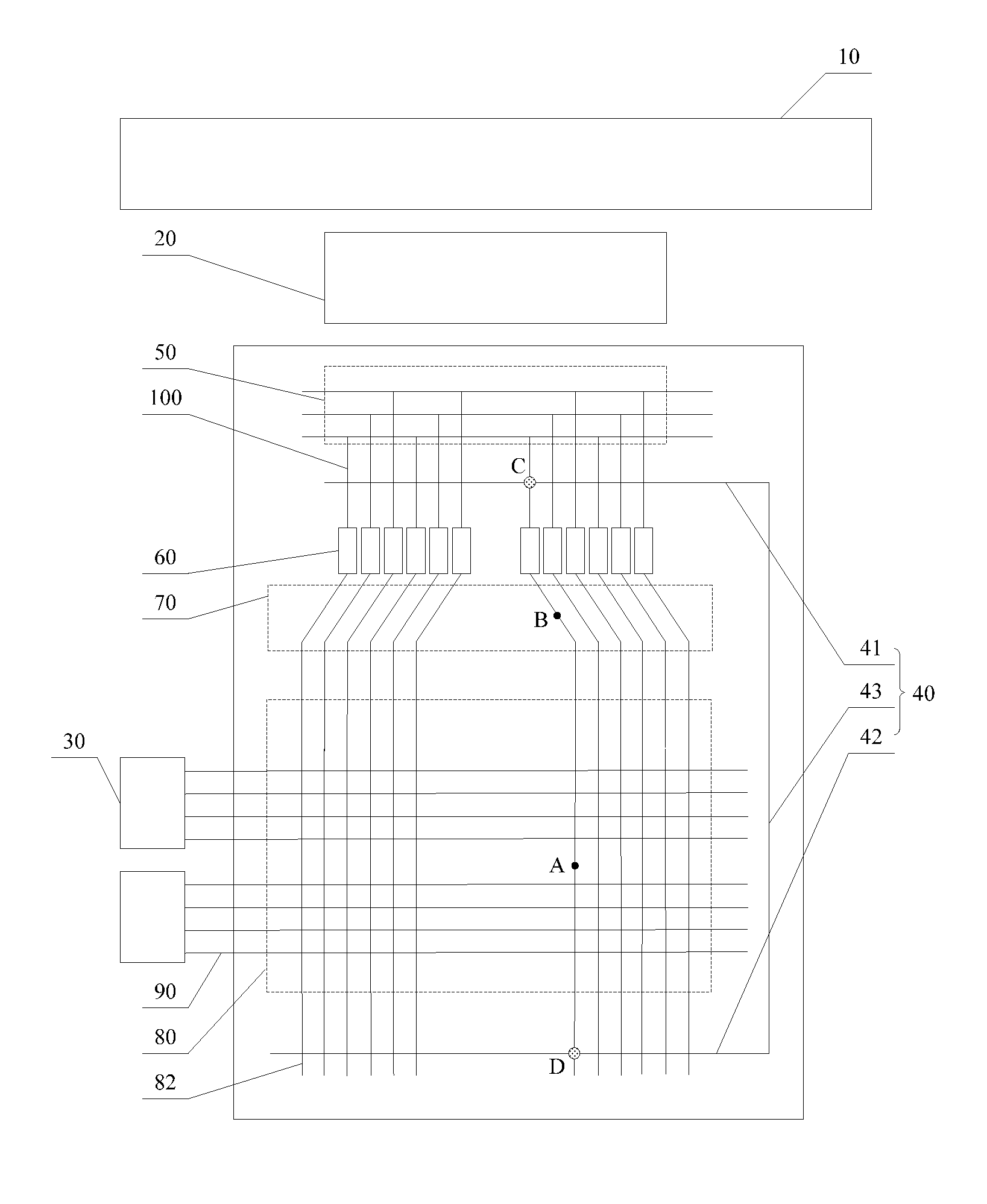
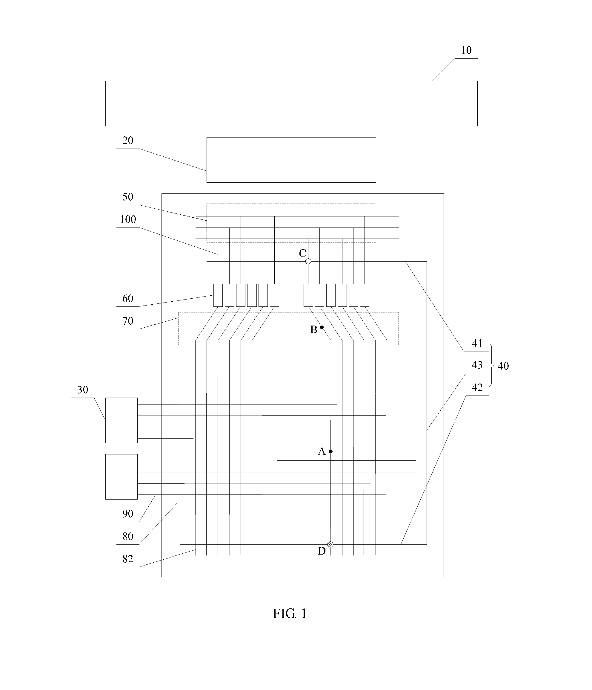
[0026]Referring to FIG. 1, which is a schematic view of a liquid crystal display in accordance with the present disclosure. The liquid crystal display in the embodiment includes a printed circuit board 10, a data driving chip 20, a scanning driving chip 30, and a liquid crystal panel. The liquid crystal panel includes a repairing line 40, a short circuit bar area 50, a number of data line pads 60, a number of scanning line pads (not shown), a wiring area 70, a displaying area 80, a number of scanning lines 90, a number of data lines 82 passing through the displaying area 80 and the wiring area 70, and a number of testing lines 100 for connecting short circuit bars arranged on the short circuit bar area 50 and the data line pads 60 in the testing of the liquid crystal display. The data driving chip 20 is fixed on a first flexible circuit board (not shown) which is respectively connected to the printed circuit board 10 and the data line pads 60. The scanning driving chip 30 is respect...

second embodiment

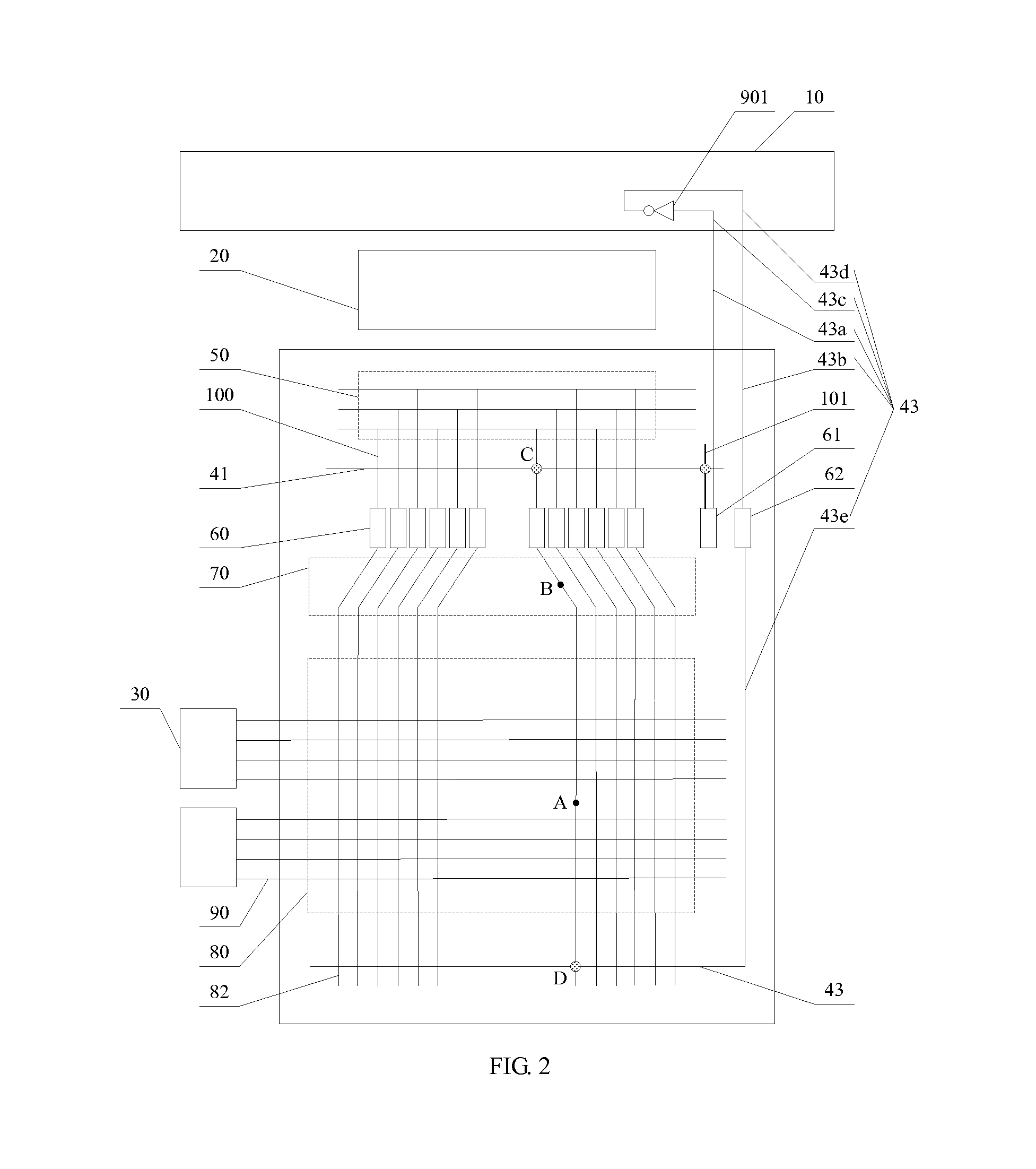
[0030]Referring to FIG. 2, which is a schematic view of a liquid crystal display in accordance with the present disclosure. The liquid crystal display in the embodiment further includes an empty testing line 101, a first empty data line pad 61, and a second empty data line pad 62. The first empty data line pad 61 is electrically connected to the empty testing line 101. The first portion 41 of the repairing line 40 isolably intersects with the testing lines 100 and the empty testing line 101. The third portion 43 includes a first connecting line 43a, a second connecting line 43b, a third connecting line 43c, a fourth connecting line 43d, and a fifth connecting line 43e. The first connecting line 43a and the second connecting line 43b are respectively arranged on the first flexible printed circuit board, and the third connecting line 43c and the fourth connecting line 43d are respectively arranged on the printed circuit board 10. The first connecting line 43a is further connected the ...


PUM


Abstract

The present disclosure provides a liquid crystal display, including at least one repairing line, a short circuit bar area, a number of data line pads, a number of testing lines for connecting short circuit bars on the short circuit bar area and the data line pads, a wiring area, a displaying area, and a number of data lines passing through the wiring area and the displaying area; first ends of the data lines being electrically connected to the data line pads and second ends of the data lines extending to be located under the displaying area; the repairing line comprising a first portion isolably intersecting with the testing lines, a second portion isolably intersecting with the second ends of the data lines, and a third portion connecting the first portion and the second portion in the repairing of a disconnected line.

Description

BACKGROUND[0001]1. Technical Field[0002]The present disclosure relates to liquid crystal displaying technologies, and particularly, to a liquid crystal display.[0003]2. Description of Related Art[0004]With the development of electrical technologies, flat displays such as liquid crystal displays, plasma displays, and OLED (Organic Light-Emitting Diode) displays have gained rapid development. Among the flat displays, the liquid crystal displays are commonly used due to advantages including light weight, small volume, and low power consumption.[0005]At present, a liquid crystal panel of a liquid crystal display generally forms a wiring area, a displaying area, and includes a number of data lines passing through the displaying area and the wiring area, a number of scanning lines, and at least one repairing line for repairing a disconnected data line. Generally, each of the repairing line includes a first portion, a second portion, and a third portion. The first portion is arranged betwe...

Claims


Application Information

Patent Timeline
IPC IPC(8): G02F1/13
CPCG02F1/1309G02F1/136259G02F1/136254G02F1/136263
Inventor DENG, MINGFENGTSAI, JUNGMAOZUANG, YIZHUANGWEN, SONGXIAN
Owner TCL CHINA STAR OPTOELECTRONICS TECH CO LTD
Learn More